B&B Electronics 3PCIU4 User Manual
Page 70
RS-422/485 Connections/Operation
64
Chapter 8
Manual Documentation Number 3PCIoUx-1008
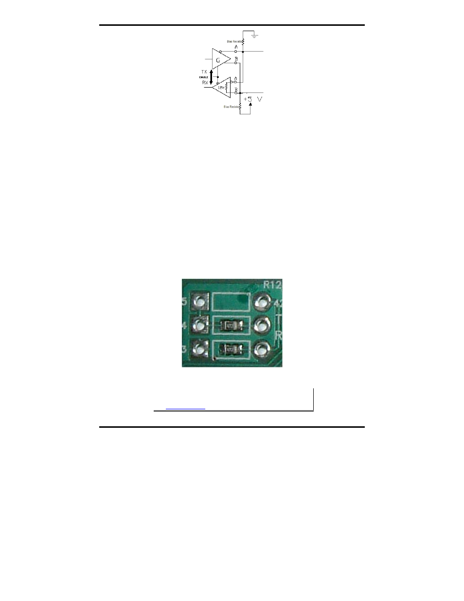
Figure 47. RS-485 Biasing Resistors
MIport RS-485 receivers come pre-biased from the factory with a 4.7 k
Ω
pull-up resistor on the RD(B)+ line and a 4.7 k
Ω pull-down resistor on the
RD(A)- line. These values are usually adequate for networks that do not
implement termination resistors and have 31 or fewer nodes. When
termination is used, biasing must be increased (resistors decreased),
calculated according to the termination value and number of nodes.
Through hole pads are provided on MIport cards for adding termination
resistors and bias resistors. The photograph below shows the layout of
through hole pads for installing termination and bias resistors. On all MIport
cards the top set of holes is for the termination resistor. The middle and
bottom sets of holes are for bias resistors. (Note the factory installed 4.7k
resistors in the photograph.) Since bias resistors are always the same value
(e.g R pullup = R pulldown = 4.7k) there is no need to identify which set of
holes is for pull up and which is for pull down.
Figure 48. Termination and Bias Resistor Placement
Note: For more information on termination, biasing and how to
calculate resistor values download the RS-422/485 Application Note
from
www.bb-elec.com