B&B Electronics 3PCIU4 User Manual
Page 61
RS-232 Connections/Operation
Manual Documentation Number 3PCIoUx-1008
Chapter 7
55
C
C
h
h
a
a
p
p
t
t
e
e
r
r
7
7
:
:
R
R
S
S
-
-
2
2
3
3
2
2
C
C
o
o
n
n
n
n
e
e
c
c
t
t
i
i
o
o
n
n
s
s
/
/
O
O
p
p
e
e
r
r
a
a
t
t
i
i
o
o
n
n
RS-232 Mode
In RS-232 Mode MIport serial ports function as buffered standard PC serial
ports and operate as DTEs (Data Terminal Equipment). RS-232 interfaces are
commonly used for communications with modems, serial printers, and
computer-controlled devices such as security equipment, bar code scanners
and point-of-sale devices.
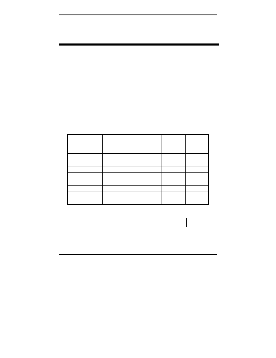
RS-232 Signal Designations and DB-9 Pinout
RS-232 Mode supports eight single-ended signal lines and signal ground. The
DB-9 male connector is configured as a standard RS-232 (DTE) serial port.
The table below shows the signal names and pin numbers.
RS-232 Signal
Name
RS-232 Signal
Description
Direction
(DTE)
DB-9M
Pin
DCD
Data Carrier Detect
Input
1
RD Receive
Data
Input
2
TD Transmit
Data
Output
3
DTR Data
Terminal
Ready
Output
4
GND Signal
Ground
------
5
DSR
Data Set Ready
Input
6
RTS Request
to
Send
Output
7
CTS
Clear to Send
Input
8
RI Ring
Indicator
Input
9
Figure 41. RS-232 Signal Designations and DB-9 Pinout
Note: Refer to Appendix B for additional cable configurations and
pinouts