B&B Electronics 3PCIU4 User Manual
Page 79
DIP Switch / Mode Settings
Manual Documentation Number 3PCIoUx-1008
Appendix A
A -1
A
A
p
p
p
p
e
e
n
n
d
d
i
i
x
x
A
A
:
:
D
D
I
I
P
P
S
S
w
w
i
i
t
t
c
c
h
h
/
/
M
M
o
o
d
d
e
e
S
S
e
e
t
t
t
t
i
i
n
n
g
g
s
s
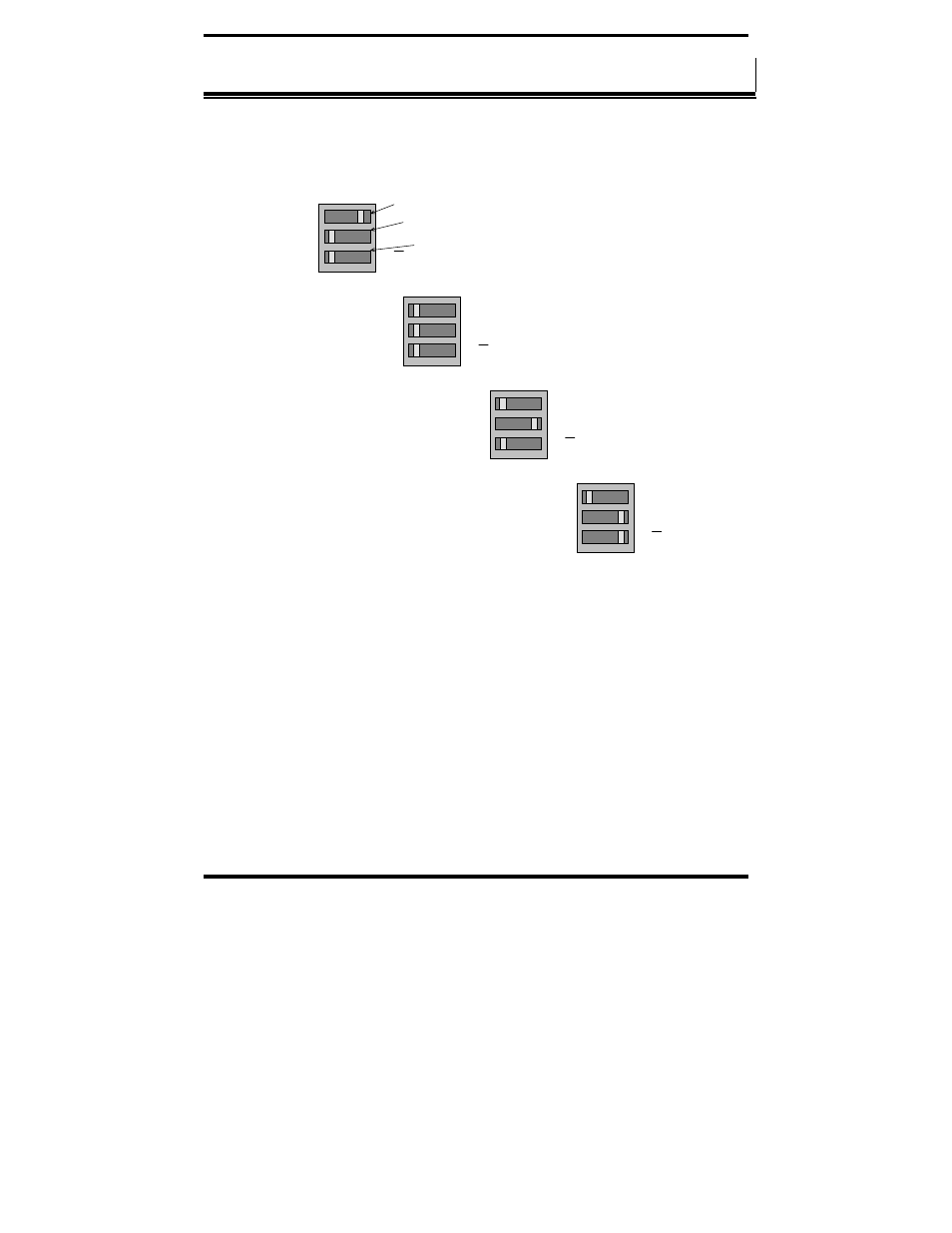
Setting the DIP Switches on RS-232/422/485 Ports
Set the DIP switches to configure the desired operating mode as follows:
422/485
TX On
RX On
232
TX SD
RX SD
Switch 1
Switch 2
Switch 3
RS-232 Mode
422/485
TX On
RX On
232
TX SD
RX SD
RS-422 Mode
422/485
TX On
RX On
232
TX SD
RX SD
4-wire RS-485 Mode
422/485
TX On
RX On
232
TX SD
RX SD
2-wire RS-485 Mode
Figure 54. RS-232/422/485 DIP Switch Settings.
DIP Switch 1 (RS-232/422/485 ports)
The top DIP switch (1) configures the port for RS-232 or RS-422/485
operation. This switch is the only one that is required to be set for RS-232
operation. The positions of switches 2 and 3 do not matter when switch 1 is
set for RS-232 operation.
DIP Switch 2 (RS-232/422/485 ports)
The middle DIP switch (2) configures the port for RS-485 or RS-422
operation. For RS-422 operation (which uses two wire pairs and sends point-
to-point or point-to-multipoints) the transmitter can be enabled all the time.
Placing the middle DIP switch in the TX ON position accomplishes this.