Bryant 345MAV User Manual
Page 28
16. Use appropriate methods to seal openings where vent pipe
passes through roof or sidewall.
D.
Extended Exposed Sidewall Pipes
Sidewall vent pipe termination may be extended beyond area
shown in Fig. 34 in outside ambient by insulating pipe as indicated
in Table 5.
1. Determine vent pipe diameter, as stated above, using total
pipe length and number of elbows.
2. Find appropriate temperature for your application and
furnace model using winter design temperature (used in
load calculations).
3. Determine required insulation thickness for exposed pipe
lengths.
NOTE:
Pipe length (ft) specified for maximum pipe lengths
located in unconditioned spaces cannot exceed total allowable pipe
length as specified in Table 4.
III.
VENT TERMINATION
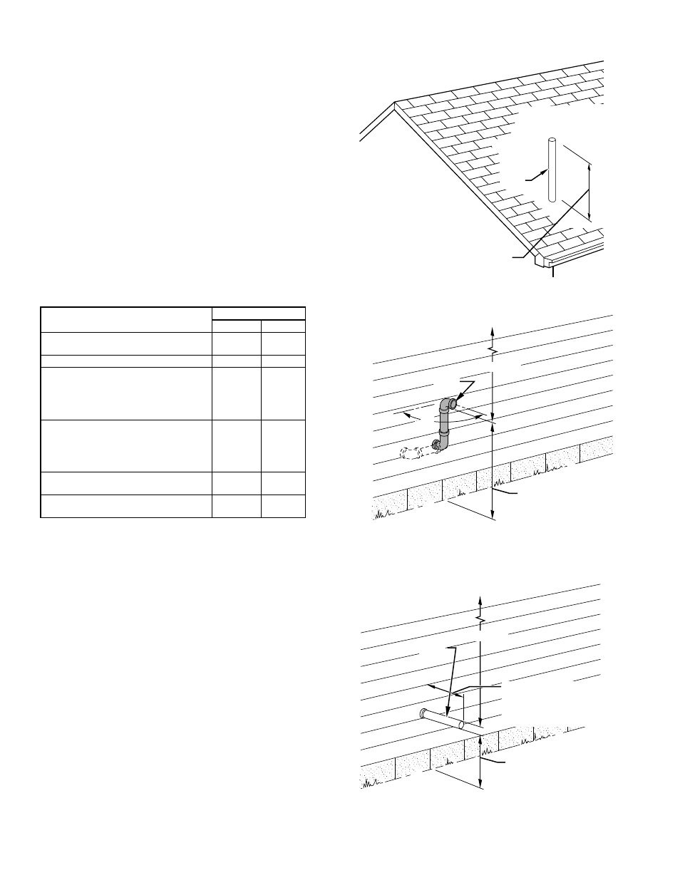
Vent pipe must terminate either through roof or sidewall. See
Table 6 for required clearances. See Fig. 33, 34, and 35 for exterior
piping arrangements.
Consideration of the following should be made when determining
an appropriate location for termination:
1. Comply with all clearance requirements stated in Table 6.
2. Termination should be positioned where vent vapors will
not damage plants/shrubs or air conditioning equipment.
3. Termination should be positioned where it will not be
damaged by or subjected to foreign objects such as stones,
balls, etc.
4. Termination should be positioned where vent vapors are not
objectionable.
IV.
MULTIVENTING
When 2 or more 345MAV Furnaces are vented near each other,
each furnace must be individually vented. NEVER common vent
or breach vent 345MAV furnaces.
CONDENSATE DRAIN
I.
GENERAL
Condensate trap is shipped installed in the blower shelf and factory
connected for UPFLOW applications. Condensate trap must be
RELOCATED for use in DOWNFLOW and HORIZONTAL
applications.
TABLE 6—VENT PIPE TERMINATION CLEARANCES
LOCATION
CLEARANCE (FT)
U.S.A.
Canada
Above grade level or above antici-
pated snow depth
1
1*
From any mechanical fresh air intake
3 above†
6
For furnaces with an input capacity
less than 100,000 Btuh–from any
non-mechanical air supply (windows
or doors which can be opened) or
combustion-air opening
4‡
1
For furnaces with an input capacity
greater than 100,000 Btuh–from any
non-mechanical air supply (windows
or doors which can be opened) or
combustion-air opening
4‡
3
From service regulator vent, electric
and gas meters, and relief equipment
4**
6††
Above grade when adjacent to public
walkway
7
7
* 18 in. above roof surface in Canada.
† Located within 10 ft in U.S.A.
‡ Horizontal or below opening. If above opening, 1 ft is allowed.
** Horizontal distance.
†† 36 in. to electric meter in Canada only.
NOTE: When locating vent termination, consideration must be given to
prevailing winds, location, and other conditions which may cause nuisance
outages.
Fig. 35—Sidewall Termination with Straight Pipe
A96210
MAINTAIN 12-IN.
CLEARANCE
ABOVE HIGHEST
ANTICIPATED SNOW
LEVEL OR GRADE,
WHICHEVER IS
GREATER.
VENT
12
″
MINIMUM
OVERHANG OR ROOF
6-IN. MINIMUM
CLEARANCE BETWEEN
WALL AND END OF VENT
PIPE.
10-IN. MAXIMUM PIPE LENGTH
Fig. 34—Sidewall Termination with 2 Elbows (Preferred)
A96192
MAINTAIN 12-IN.
CLEARANCE
ABOVE HIGHEST
ANTICIPATED SNOW
LEVEL OR GRADE,
WHICHEVER IS
GREATER.
90
°
VENT
12
″
MINIMUM
OVERHANG OR ROOF
Fig. 33—Roof Termination (Preferred)
A96191
ROOF
VENT
MAINTAIN 12-IN. MINIMUM
CLEARANCE ABOVE HIGHEST
ANTICIPATED SNOW LEVEL.
MAXIMUM OF 24 IN.
ABOVE ROOF.
—28—