Bryant Gas Heating/Electric Cooling Units 581B User Manual
Page 10
3. Voltage to compressor terminals during operation must
be within voltage range indicated on unit nameplate (also
see Tables 3A and 3B). On 3-phase units, voltages be-
tween phases must be balanced within 2% and the cur-
rent within 10%. Use the formula shown in Tables 3A
and 3B, Note 2, to determine the percent voltage im-
balance. Operation on improper line voltage or exces-
sive phase imbalance constitutes abuse and may cause
damage to electrical components. Such operation would
invalidate any applicable warranty.
4. Insulate low-voltage wires for highest voltage con-
tained within conduit when low-voltage control wires are
run in same conduit as high-voltage wires.
5. Do not damage internal components when drilling through
any panel to mount electrical hardware, conduit, etc.
NOTE:
If accessory thru-the-bottom connections and roof curbs
are used, refer the Thru-the-Bottom Installation Instruc-
tions for information on power wiring.
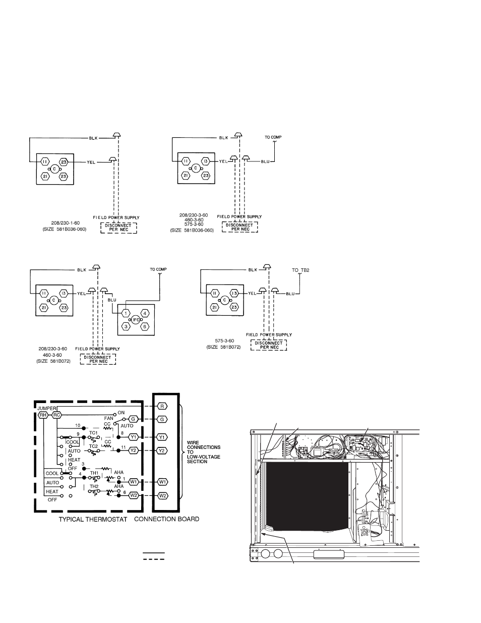
Fig. 13 — Power Wiring Connections
LEGEND
AHA — Adjustable Heat Anticipator
TC
—
Thermostat-Cooling
CC
— Cooling Compensator
TH
—
Thermostat-Heating
RC
— 24-v Cooling
Field Wiring
RH
— 24-v Heating
Factory Wiring
NOTE: Connect Y2 when unit is equipped with an integrated
economizer.
Fig. 14 — Low-Voltage Connections With or
Without Economizer or Two-Position Damper
LOW VOLTAGE
CONNECTIONS
(SCREW TERMINALS)
INTEGRATED GAS UNIT
CONTROLLER (IGC)
HOLE IN END PANEL (HIDDEN)
RACEWAY
Fig. 15 — Field-Control Wiring Raceway
LEGEND
C
— Contactor
COMP — Compressor
EQUIP — Equipment
GND
— Ground
IFC
— Indoor (Evaporator) Fan
Contactor
NEC
— National Electrical Code
—10—