Bryant 541A User Manual
Page 9
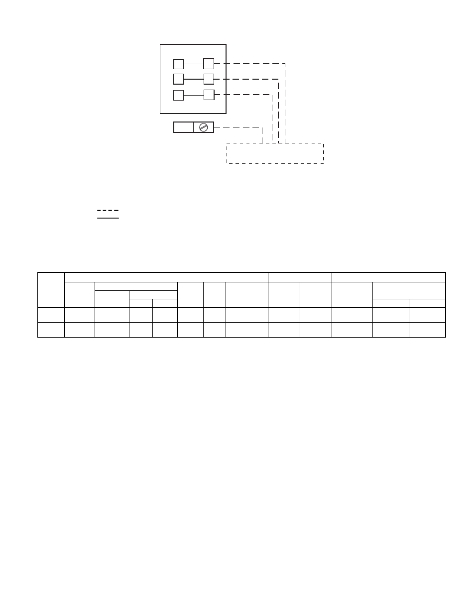
Table 7 — Electrical Data (3 Ph/60 Hz)
541A
UNIT
COMPRESSOR
FAN MOTORS (Single-Phase)
Model
Volts
MCA
ICF
MOCP
(Amps)
Fuse Only
RLA
LRA
Total
Fans
FLA (ea)
Fan No.
Name-
plate
Supplied*
Min
Max
1
2
120
501
208-230
187
253
62.5
178
100
43.6
170
2
4.3
3.7
601
460
414
528
29.1
81
40
20.0
77
2.3
1.9
180
501
208-230
187
253
87.5
274
125
63.6
266
2
4.3
3.7
601
460
414
528
40.7
124
60
29.3
120
2.3
1.9
LEGEND
FLA
— Full Load Amps (fan motors)
ICF
— Maximum Instantaneous Current Flow during start-up
(LRA of compressor plus total FLA of fan motors)
LRA
— Locked Rotor Amps
MCA
— Minimum Circuit Amps per NEC Section 430-24
MOCP — Maximum Overcurrent Protection (fuse only)
RLA
— Rated Load Amps (compressor)
*Units are suitable for use on electrical systems where voltage supplied
to the unit terminals is not below or above the listed limits.
NOTES:
1. MCA and MOCP values are calculated in accordance with NEC
(National Electric Code), Article 440.
2. Motor RLA and FLA values are established in accordance with
UL (Underwriters’ Laboratories) Standard 1995.
EQUIP GND
21
22
23
13
12
11
DISCONNECT PER NEC
OR LOCAL CODE
TERMINAL BOARD (TB1) IN
UNIT CONTROL BOX
LEGEND
CAP
— Capacitor
EQUIP — Equipment
GND
— Ground
NEC
— National Electrical Code
Field Wiring
Factory Wiring
Fig. 9 — Main Power Supply Wiring
—9—