Bryant 541A User Manual
Page 5
B. Refrigerant Line Design and Sizing
Consider the length of the piping required between the out-
door and indoor units. The maximum allowable line length is
100 ft. Select proper liquid and vapor line sizes from Table 4.
Contact your local representative if assistance is required for
design details and proper piping practices.
Table 4 — Piping Selection and Refrigerant
Charge Data
OUTDOOR
UNIT
541A
LENGTH 0F PIPING — FT*
MAXIMUM
LIQUID
LINE OD
(in.)
0-25
25-60
60-100†
Line Size (in. OD)
L
V
L
V
L
V
120
5
⁄
8
1
1
⁄
8
5
⁄
8
1
3
⁄
8
5
⁄
8
1
5
⁄
8
5
⁄
8
180
5
⁄
8
1
3
⁄
8
3
⁄
4
1
5
⁄
8
3
⁄
4
1
5
⁄
8
3
⁄
4
Approximate System Charge
lb**
Maximum
Charge —
lb
120
30
38
46
48
180
37
45
59
62
LEGEND
L — Liquid Line
V — Vapor Line
*Approximately 4 elbows assumed in determining pipe sizes.
†Maximum length of interconnecting piping is 100 ft.
**Approximate system charge is for estimating only. It includes charge
requirements for one outdoor unit, matching indoor coil, and intercon-
necting piping. See Preliminary Charge section on page 10.
NOTE: If there is a vertical separation between indoor and outdoor units,
see Table 3. Double vapor line riser may be required.
Carefully evaluate any vapor risers at minimum load condi-
tions to ensure proper compressor oil return. If the indoor
unit is above the outdoor unit, the riser will function as a hot
gas riser. If the outdoor unit is above the indoor unit, the riser
is a suction riser. Design and construct a double riser if nec-
essary. Contact your local representative if assistance is
required.
C. Liquid Line Piping Procedure
Pipe the system liquid line as follows:
WARNING:
Unit is pressurized with a holding charge
of refrigerant. Recover R-22 holding charge before re-
moving runaround liquid piping loop. Failure to re-
cover holding charge before removing piping loop could
result in equipment damage and severe injury.
1. Open service valves in sequence:
a. Discharge service valve on compressor.
b. Suction service valve on compressor.
c. Liquid line valve.
2. Remove
1
⁄
4
-in. flare cap from liquid valve Schrader port.
3. Attach refrigerant recovery device and recover holding
charge.
4. Remove runaround loop.
5. Connect system liquid line from liquid connection of out-
door (541A) unit to indoor unit liquid line connections.
See Fig. 5 for typical piping and wiring. Select proper
field-supplied bi-flow filter driers and install in the liq-
uid line. See Fig. 6. Install a field-supplied liquid mois-
ture indicator between the filter drier(s) and the liquid
connections on the indoor (524A-H) unit. Braze or silver
alloy solder all connections. Pass nitrogen or other inert
gas through piping while making connections to pre-
vent formation of copper oxide. (Copper oxides are ex-
tremely active under high temperature and pressure.
Failure to prevent collection of copper oxides may re-
sult in system component failures.)
D. Vapor Line Piping Procedure
Connect system vapor line to the vapor line stub on the out-
door unit and the vapor stubs on the indoor unit. At the in-
door unit, construct vapor piping branches as shown in Fig. 7
for good mixing of the refrigerant leaving the indoor coil dur-
ing cooling. This will ensure proper TXV (thermostatic ex-
pansion valve) bulb sensing.
Where vapor line is exposed to outdoor air, line must be in-
sulated. See Table 5 for insulation requirements.
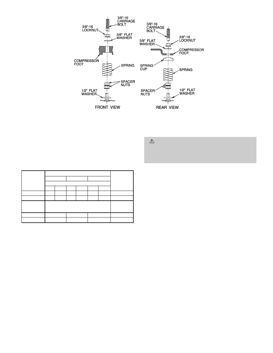
Fig. 4 — Compressor Mounting
—5—