Bryant 541A User Manual
Page 4
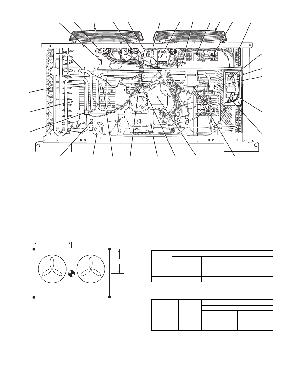
Table 2 — Weight Distribution
UNIT
541A
WEIGHT — lb
Total
Operating
Weight
Support Point
(Fig. 3)
1
2
3
4
120
750
147
228
228
147
180
803
158
243
244
158
Table 3 — Maximum Vertical Separation*
OUTDOOR
UNIT
541A
INDOOR
UNIT
524A-H
DISTANCE — FT
Indoor Unit
Above Outdoor
Unit
Below Outdoor
Unit
120
120
50
50
180
180
80
80
*Vertical distance between indoor and outdoor units.
1
2
3
4
5
6
7
8
9
10
11
12
13
14
15
16
17
18
19
20
21
22
23
24
25
26
27
28
LEGEND
1 — Defrost Board/Time Guard
ா
II Control
2 — Fuse
3 — Fan No. 1
4 — Signal-LOC™ Device
5 — Outdoor-Fan Relay
6 — Outdoor-Fan Contactor
7 — Compressor Contactor
8 — Fan Motor Capacitors
9 — Circuit Breaker
10 — Fan No. 2
11 — Power Terminal Block
12 — Control Terminal Block
13 — Compressor Lockout (CLO2 for
Crankcase Heater)
14 — Control Relay (CR3)
15 — Liquid Line Solenoid
16 — Control Relay (CR2)
17 — No Dump Relay (NDR)
18 — Oil Pressure Switch
19 — Fusible Plug (hidden)
20 — High-Pressure Switch
21 — Compressor
22 — Capacity Control Solenoid
23 — Filter Drier
24 — Muffler
25 — Oil Solenoid
26 — Reversing Valve
27 — Accumulator
28 — Coil
Fig. 2 — Component Locations
2
1
4
3
541A120, 180
38 1/4"
26 11/16"
Fig. 3 — Weight Distribution
—4—