Connecting the units – Pioneer DEH-P8400MP User Manual
Page 4
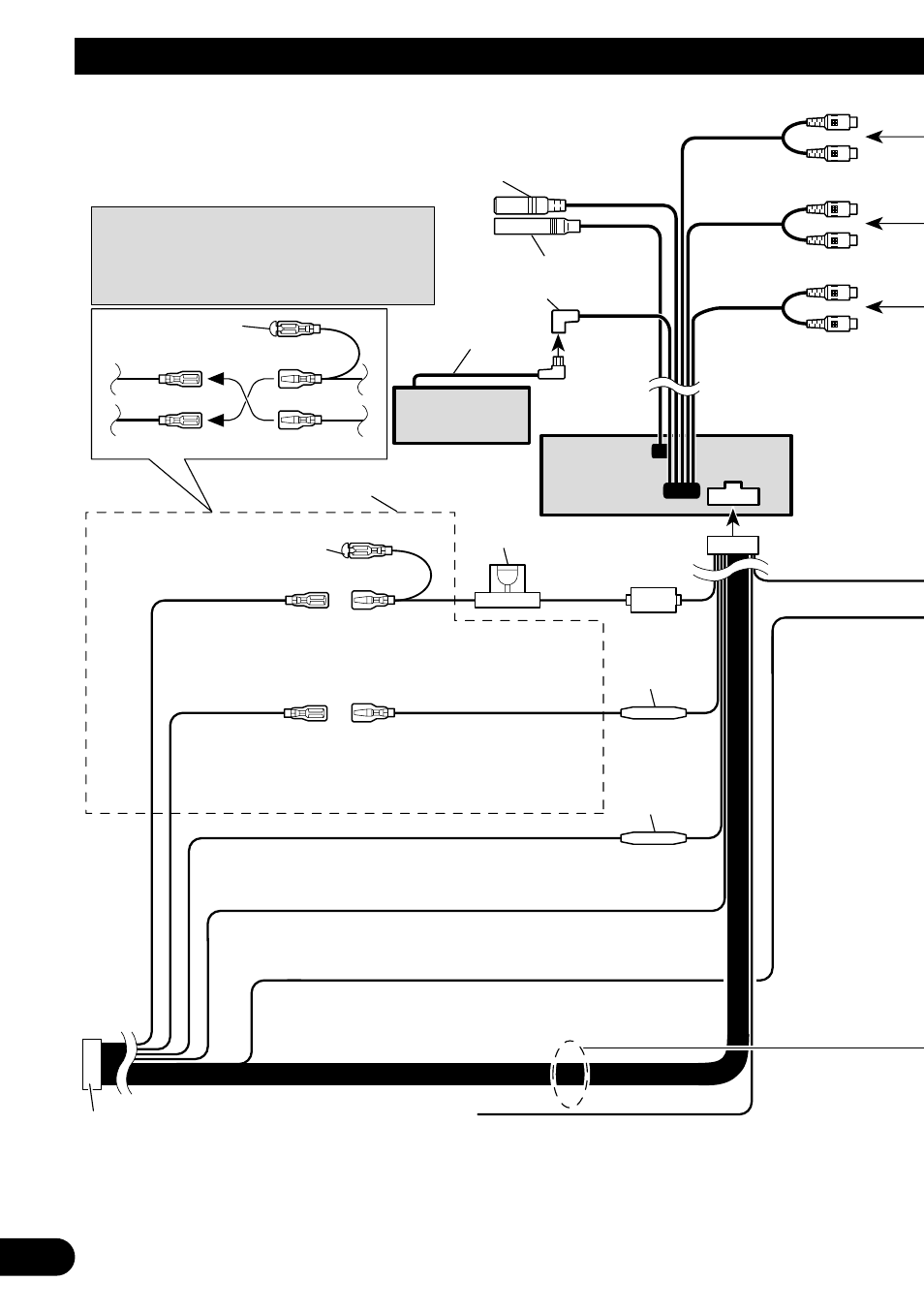
Note:
Depending on the kind of vehicle, the function
of 3* and 5* may be different. In this case, be
sure to connect 2* to 5* and 4* to 3*.
Connect leads of the same
color to each other.
Cap (1*)
When not using this terminal,
do not remove the cap.
ISO connector
Fuse holder
1*
2*
4*
3*
5*
Yellow (2*)
To terminal always supplied
with power regardless of
ignition switch position.
Red (4*)
To electric terminal controlled
by ignition switch (12 V DC)
ON/OFF.
Yellow (3*)
Back-up
(or accessory)
Red (5*)
Accessory
(or back-up)
Black (ground)
To vehicle (metal) body.
Orange/white
To lighting switch terminal.
Blue/white
To system control terminal of the power amp
(max. 300 mA 12 V DC).
Note:
In some vehicles, the ISO connector may be
divided into two. In this case, be sure to
connect to both connectors.
Fuse resistor
Fuse resistor
Multi-CD player
(sold separately)
Yellow/black
If you use a cellular telephone, connect it via the
Audio Mute lead on the cellular telephone. If not,
keep the Audio Mute lead free of any connections.
IP-BUS cable
TEL terminal
Refer to handsfree telephone unit’s manual
(sold separately).
Subwoofer output
or Non Fading Output
(SUBWOOFER or
NON-FADING
OUTPUT)
Front output
(FRONT OUTPUT)
Rear output
(REAR OUTPUT)
This Product
Antenna jack
15 cm
15 cm
15 cm
IP-BUS input (Blue)
15 cm
23 cm
15 cm
3
Connecting the Units