ADTRAN NetVanta 2400 User Manual
Page 2
Quick Start Guide, 61202361L2-13C, November 2005
Technical Support 1-888-4ADTRAN (1-888-423-8726)
Copyright © 2005 ADTRAN, All Rights Reserved
For more detailed documentation, visit us online at
.
Quick Start Guide
®
NetVanta 2300/2400
P/N 1202366L2, 1202367L2
E
NABLE
T
ELNET
A
CCESS
The following steps create a password of adtran for Telnet access. By default, Telnet access is
enabled with a password of password.
1.
Verify that the prompt of your unit displays (config)#.
2.
Enter line telnet 0 4 to change the configuration parameters for the Telnet sessions.
3.
Enter login to initiate Telnet access.
4.
Enter password adtran to change the login password for the Telnet sessions.
5.
Enter exit to return to the Global Configuration mode.
6.
Verify that the prompt of your unit displays (config)#.
7.
Enter do write memory to save the current configuration.
C
ONFIGURE
Y
OUR
A
PPLICATION
More detailed documentation for configuring your ADTRAN unit is provided on the ADTRAN OS
System Documentation CD included in your shipment. For more detail on hardware setup, refer to
the Hardware Installation Guide. For more detail on configuring your system, refer to the ADTRAN
Operating System (AOS) Command Reference Guide, configuration guides, and technical support
notes.
Depending on your configuration, you may need to set a default gateway
as well using the (config)#ip default gateway command. If IP routing is
enabled on the unit, do NOT set a default gateway.
Important: For additional details on product features, specifications,
installation, and safety, refer to the appropriate Hardware Installation
Guide on the ADTRAN OS System Documentation CD shipped with the
base unit and available online at www.adtran.com.
C
ONSOLE
P
INOUTS
Pin
Name
Description
1
DCD
Data Carrier Detect (output)
2
RD
Receive Data (output)
3
TD
Transmit Data (input)
4
DTR
Data Terminal Ready (input)
5
SG
Signal Ground
6
DSR
Data Set Ready (output)
7
—
Unused
8
CTS
Clear to Send (output)
9
—
Unused
E
THERNET
P
INOUTS
Pin
Name
Description
1
TX1
Transmit Positive
2
TX2
Transmit Negative
3
RX1
Receive Positive
4, 5
—
Unused
6
RX2
Receive Negative
7, 8
—
Unused
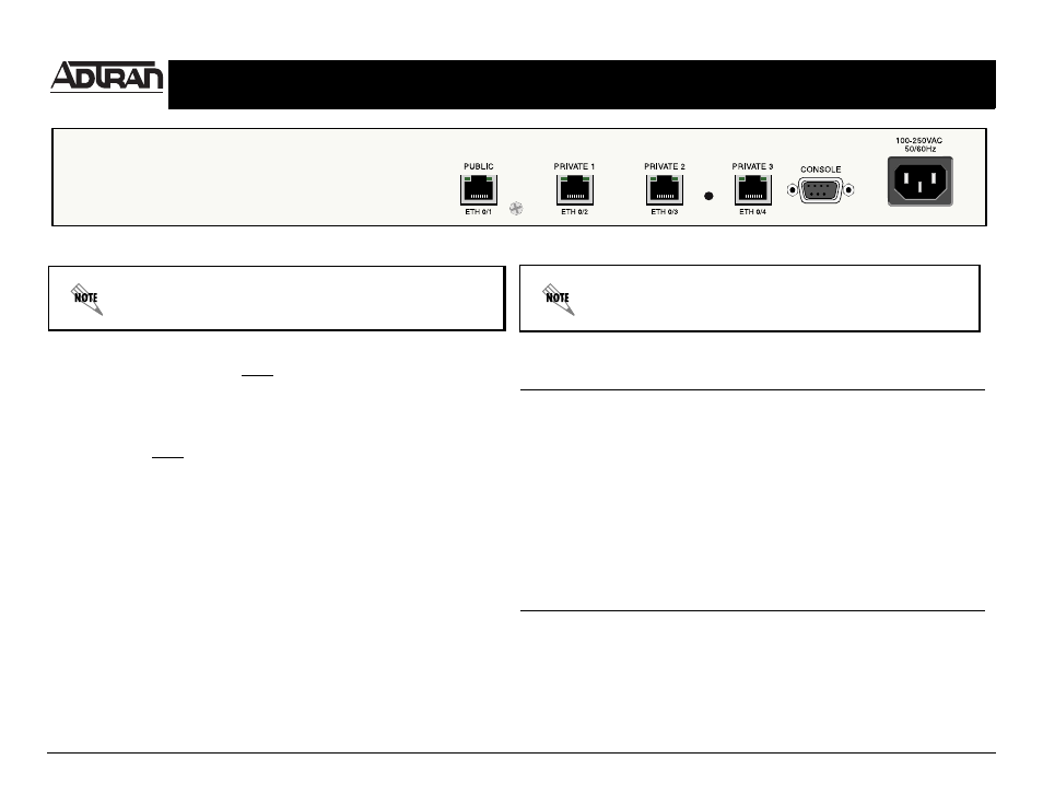
NetVanta 2300/2400 Rear Panel Layout