Set-up – American Audio Pro Scratch 1 User Manual
Page 4
1. Checking the Contents
Be sure your Pro Scratch 1 was shipped with the following:
1) Pro Scratch 1 Professional CD player.
2) Operating instructions (this booklet).
3) One (1) set of RCA cables.
4) One (1) 1/8” mini plug.
5) Warranty card.
2. Installing the Units
Place your unit on a flat surface or mount it in a flat surface case
3. Connections
1) Be sure the power is disconnected.
2) Connect the included RCA cable from your Pro Scratch 1 outputs to the inputs on your mixer.
3) Use the supplied 1/8” mini plug cable to connect your Pro Scratch 1 to a mini jack connection (A or B ) on a
compatible American DJ “Fader Q Start” mixer. (This will enable the Fader “Q” Start function - See “Q” start
control pg. 5)
CAUTION:
• Be sure to use the supplied control cables. Using other types of cable may result in unit damage
• Be sure the power is off when connecting the control cables, otherwise the units may not work properly.
SET-UP
American DJ
®
AUDIO • Pro Scratch 1™ INSTRUCTION MANUAL • PAGE 4
• Avoid high temperatures. Allow for sufficient heat dispersion when installed in a case.
• Handle the power cord carefully.
• Hold the power cord from the plug when unplugging the cord. Never pull from the cable!
• Keep the unit free from moisture, water, and dust.
• Unplug the power cord when not using the unit for a long periods of time.
• Do not obstruct the ventilation holes. (For units with ventilation holes.)
• Do not allow foreign material to enter the unit.
• Do not let insecticides, benzene, or thinner come in contact with the surface of the unit.
• Never disassemble or modify your unit in any way, doing so will void your manufactures warranty.
GENERAL NOTES ON USE
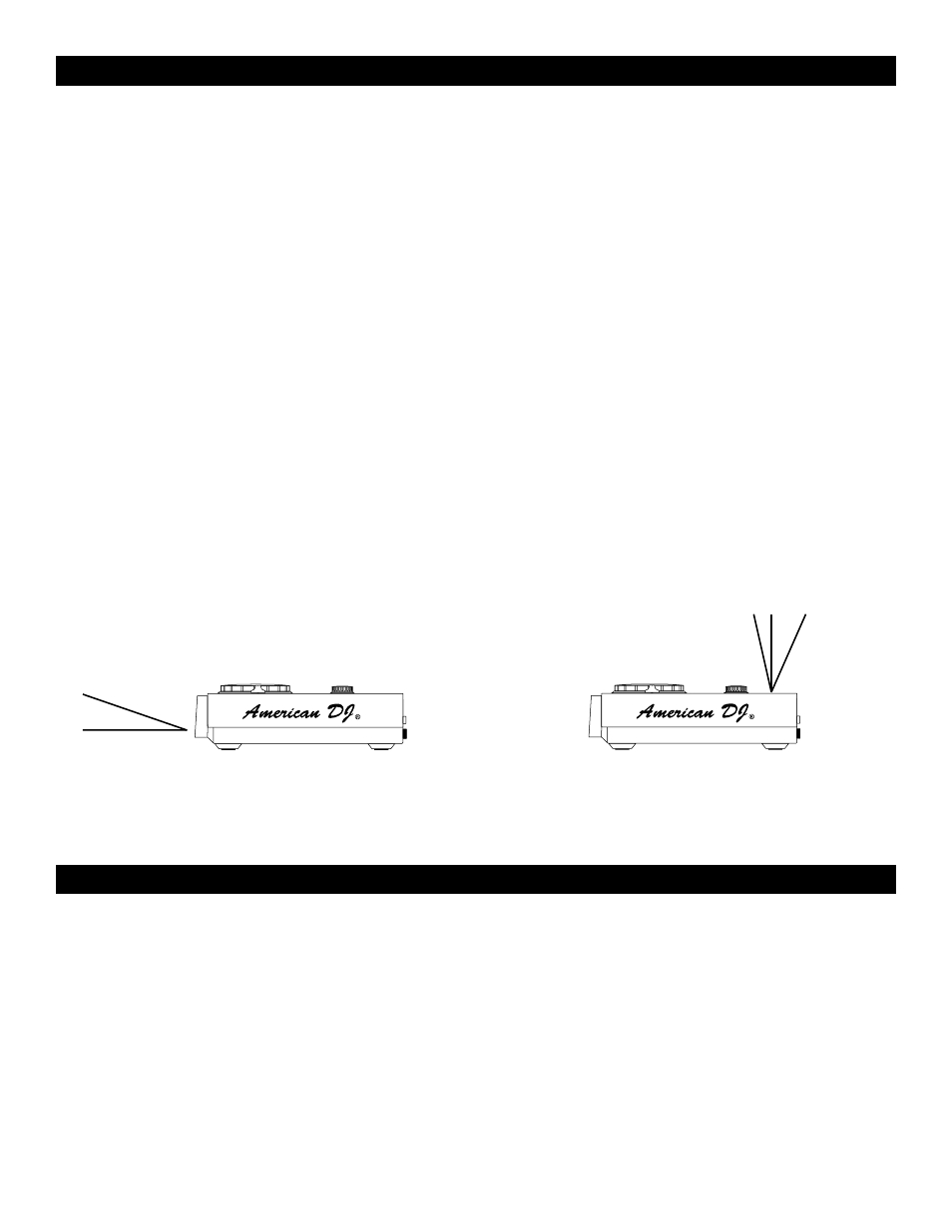
CAUTION:
• The player will work normally when the main unit is
mounted with the front panel within 15 degrees of the
vertical plane If the unit is tilted excessively, disks
may not be loaded or unloaded properly.
(Figure 1)
CAUTION:
• The LCD is designed to be clearly visible within the
angles shown in Figure 2. Mount the control unit
so that the visual angle is within this range.
Figure 2
50˚
10˚
Figure 1
15˚