Installation & maintenance instructions, Pilot operated regulator – Norgren R24P Series User Manual
Page 2
R24
Installation & Maintenance
Instructions
WARNING
These products are intended for use in industrial
compressed air systems only. Do not use these products
where pressures and temperatures can exceed those listed
under Technical Data.
If outlet pressure in excess of the regulator pressure
setting could cause downstream equipment to rupture or
malfunction, install a pressure relief device downstream of
the regulator. The relief pressure and flow capacity of the
relief device must satisfy system requirements.
The accuracy of the indication of pressure gauges can
change, both during shipment (despite care in packaging)
and during the service life. If a pressure gauge is to be
used with these products and if inaccurate indications may
be hazardous to personnel or property, the gauge should be
calibrated before initial installation and at regular intervals
during use.
Before using these products with fluids other than air,
for non industrial applications, or for life-support systems
consult Norgren.
DISASSEMBLY
1. Regulator can be disassembled without removal from air
line.
2. Shut off inlet pressure to pilot regulator and to the R24.
Reduce pressure in inlet and outlet lines to zero.
3. Turn pilot regulator adjustment counterclockwise to
remove all force on regulating spring.
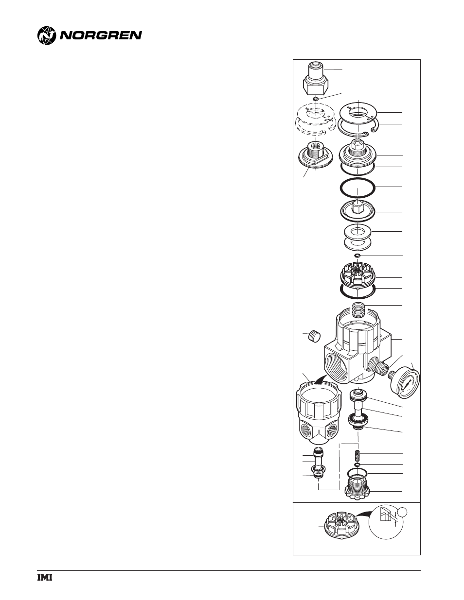
4. Disassemble in general accordance with the item numbers
on exploded view. On early models, unscrew adapter (1),
then remove o-ring (2). Current models do not use these
items.
WARNING
Prior to performing step 5, make certain air
pressure upstream and downstream of the R24
is at zero psi.
5. Use retaining ring pliers to remove the top plate (3) and
retaining ring (4). Pull cap (5 or 6) and o-ring (7) from
body.
6. Pull upper and lower piston assemblies (8 thru 13) from
body. Remove spring (14).
7. Unscrew bottom plug (15) to gain access to the parts (16
thru 23) located in the lower portion of the body.
CLEANING
1. Clean parts with warm water and soap.
2. Rinse and dry parts. Blow out internal passages in body
(24, 25) with clean, dry compressed air.
3. Inspect parts. Replace those found to be damaged.
ASSEMBLY
1. Lubricate o-rings and surfaces in contact with o-rings with
a light coat of good quality o-ring grease.
2. Place spring (14) in position in the body, then place the
upper and lower piston assembly (8 thru 13 *) in the
body. Place o-ring (7) in position on the cap (5 or 6) then
place cap in body.
3. Use retaining ring pliers to install retaining ring (4) and
top plate (3).
WARNING
Make sure retaining ring (4) is fully seated in the
groove in body.
4. On early models, install o-ring (2) and air pilot adapter (1).
5. Install lower section parts (16 thru 23) in body.
6. Torque Table
Item
Torque Inch-Pounds (Nm)
1 (adapter)
50 to 75 (5.6 to 8.5)
12 (Bottom plug)
20 to 30 (2.3 to 3.4)
* Two washers (10) are used on current R24 regulators.
Three washers were used on early R24 regulators
manufactured from September, 1993 to March, 1994. The
design of the piston (11) was changed in early 1994, and
one washer was eliminated. The washer support ribs on
the early pistons (Detail A of exploded view) are recessed
approximately 0.188" (5mm). The support ribs on current
pistons are recessed approximately 0.063" (2mm) . Use
only 2 washers (10) when replacing the early piston with a
current piston.
1
5
2
3
4
6
7
9
8
10
27
24
26
14
23
22
20
21
17
15
28
18
19
11
13
11
A
0.188"
(5mm)
25
16
19
12
a subsidiary of IMI plc
IM-414.240.02
(2/02)
Pilot Operated Regulator
© Norgren 2002