Norgren R24P Series User Manual
Installation & maintenance instructions, Pilot operated regulator
R24
Installation & Maintenance
Instructions
Warning - Feedback Pilot Regulators
Norgren manufacturers two types of feedback
pilot regulators (the R41 and the 11-104). Use
the R41, the 11-104-002, or the 11-104-003
feedback pilot regulator to control outlet
pressures greater than 100 psig (7 bar). Use
the Norgren 11-104-001 feedback pilot
regulator to control outlet pressures at or less
than 100 psig (7bar). The feedback line must
sense R24 outlet pressure and must be
connected before turning on air pressure. If
the feedback line is not connected, R24 outlet
pressure will rapidly increase to inlet pressure
when the feedback pilot adjusting knob is
turned clockwise.
4. Install a pressure gauge in a gauge port on the R24, or
to the application point downstream of the R24. Do not
connect the gauge to the pilot pressure line, as this
pressure is not the same as the R24 outlet pressure. Locate
the gauge next to the pilot regulator. Plug unused gauge
ports.
5. Install a general purpose filter upstream of the regulator.
ADJUSTMENT
1. Before applying inlet pressure to regulators, turn pilot
regulator adjustment counterclockwise to remove all
force on regulating spring.
2. Apply inlet pressure, then turn pilot regulator adjustment
clockwise to increase and counterclockwise to decrease
pressure setting.
3. Always approach the desired pressure from a lower
pressure. When reducing from a higher to a lower
setting, first reduce to some pressure less than that
desired, then bring up to the desired pressure.
1
5
2
3
4
6
7
9
8
10
27
24
26
14
23
22
20
21
17
15
28
18
19
11
13
11
A
0.188"
(5mm)
25
16
19
12
a subsidiary of IMI plc
IM-414.240.01
(2/02)
Replaces NIP-245
Pilot Operated Regulator
© Norgren 2002
Figure 2. Feedback Pilot Installation
SUPPLY
AIR
OUTLET AIR
CONVENTIONAL
PILOT REGULATOR
PILOT OPERATED
REGULATOR
PILOT
PRESSURE
LINE
SUPPLY
AIR
Figure 1. Conventional Pilot Installation
SUPPLY
AIR
FEEDBACK
PILOT REGULATOR
PILOT
PRESSURE
LINE
FEEDBACK
LINE
SUPPLY
AIR
OUTLET
AIR
PILOT OPERATED
REGULATOR
TECHNICAL DATA
Fluid: Compressed air
Inlet pressure range: 10 psig (0.7 bar) to 300 psig (20
bar). For best performance, inlet pressure should be
at least 10 psig (0.7 bar) greater than the desired
regulated pressure, but must not exceed the specified
maximum.
Operating temperature: 0° to +175°F (-20° to +80°C).
Air supply must be dry enough to avoid ice formation
at temperatures below +35°F (+2°C).
Typical flow at 150 psig (10.3 bar) inlet pressure,
90 psig (6.3 bar) set pressure, and 15 psig (1 bar)
droop from set:
1/2" ports:220 scfm (104 dm
3
/s)
1-1/4" ports: 700 scfm (330 dm
3
/s)
Maximum bleed rate at 50 psig (3.5 bar) outlet
pressure: 0.031 scfm (0.015 dm
3
/s). Maximum bleed
rate occurs under dead-end (no flow) conditions.
Port sizes:
Main
Gauge
Pilot
1/4"
1/4"
1/4"
3/8"
3/8"
1/4"
1/2", 3/4", 1", 1-1/4"
1/2"
1/4"
Thread type:
Main and gauge ports: PTF, ISO G, or ISO Rc
Pilot port: PTF with PTF main ports, ISO G with
ISO G and ISO Rc main ports
Materials:
Body, top cap: Zinc
Main valve, adjusting screw: Brass
Pilot valve, relief valve, bottom plug: Acetal
Elastomers: Nitrile
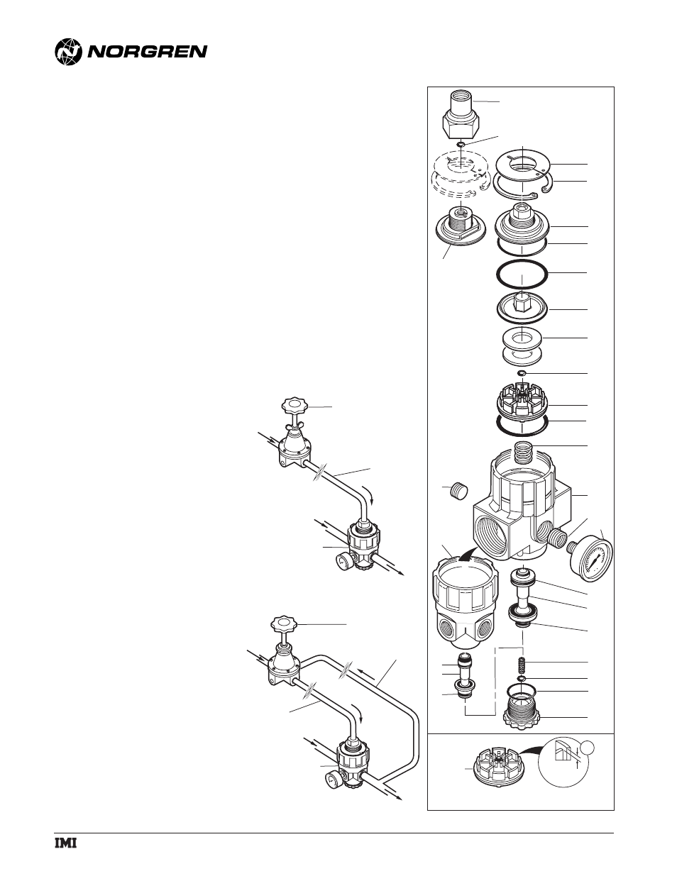
REPLACEMENT ITEMS
Service kit - 1/4", 3/8" 1/2" ported regulators
Items 2, 7, 9, 12, 13, 16, 17, 18, 19, 23 ..............5292-54
Service kit - 3/4", 1", 1-1/4" ported regulators
Items 2, 7, 9, 12, 13, 17, 20, 21, 22, 23 ..............5292-55
PANEL MOUNTING DIMENSIONS
Panel mounting hole diameter: 1.26" (32 mm)
Maximum panel thickness: 0.12" (3 mm)
INSTALLATION
1. Shut off air pressure. Install regulators in air line -
●
upstream of lubricators and cycling valves.
●
at any angle.
●
install the R24 pilot operated regulator as close as
possible to the device being serviced.
●
install the pilot regulator at any convenient, accessible
location.
2. Use pipe thread sealant on male threads only when
making the following pipe connections. Do not allow
sealant to enter interior of regulator.
●
Connect inlet and outlet air lines to R24 main ports
with air flow in direction of arrow on body.
●
Connect inlet and outlet air lines to the main ports of a
relieving type pilot regulator. The inlet port of the R40
and R41 is marked IN, and the outlet port is marked
OUT. The direction of air flow thru the 11-104 pilot is
indicated by an arrow on the bottom of the body.
●
Connect the outlet of the pilot regulator to the pilot port
in the top cap of the R24. This is the pilot pressure line.
3.Special Instructions for a Feedback Pilot:
Connect one end of the feedback line to the feedback port
on the pilot regulator. The feedback port on the R41 is
marked FDBK. The 11-104 has two 1/8" PTF feedback
ports. Plug the unused feedback port. Connect the other
end of the feedback line to a gauge port on the R24 or, if
maximum precision pressure regulation is desired, to the
application point downstream of the R24. Keep the
feedback line as short as possible and unrestricted. Use
1/4" or 3/8 " OD copper tube for the feedback line. Plug
unused gauge ports.