Front panel connector: jfp1, Ipmb connector: j_ipmb1 – MSI MS-91C2 Series User Manual
Page 25
2-13
Hardware Setup
Front Panel Connector: JFP1
This connector is designed for electrical connection to the front panel switches and
LEDs.
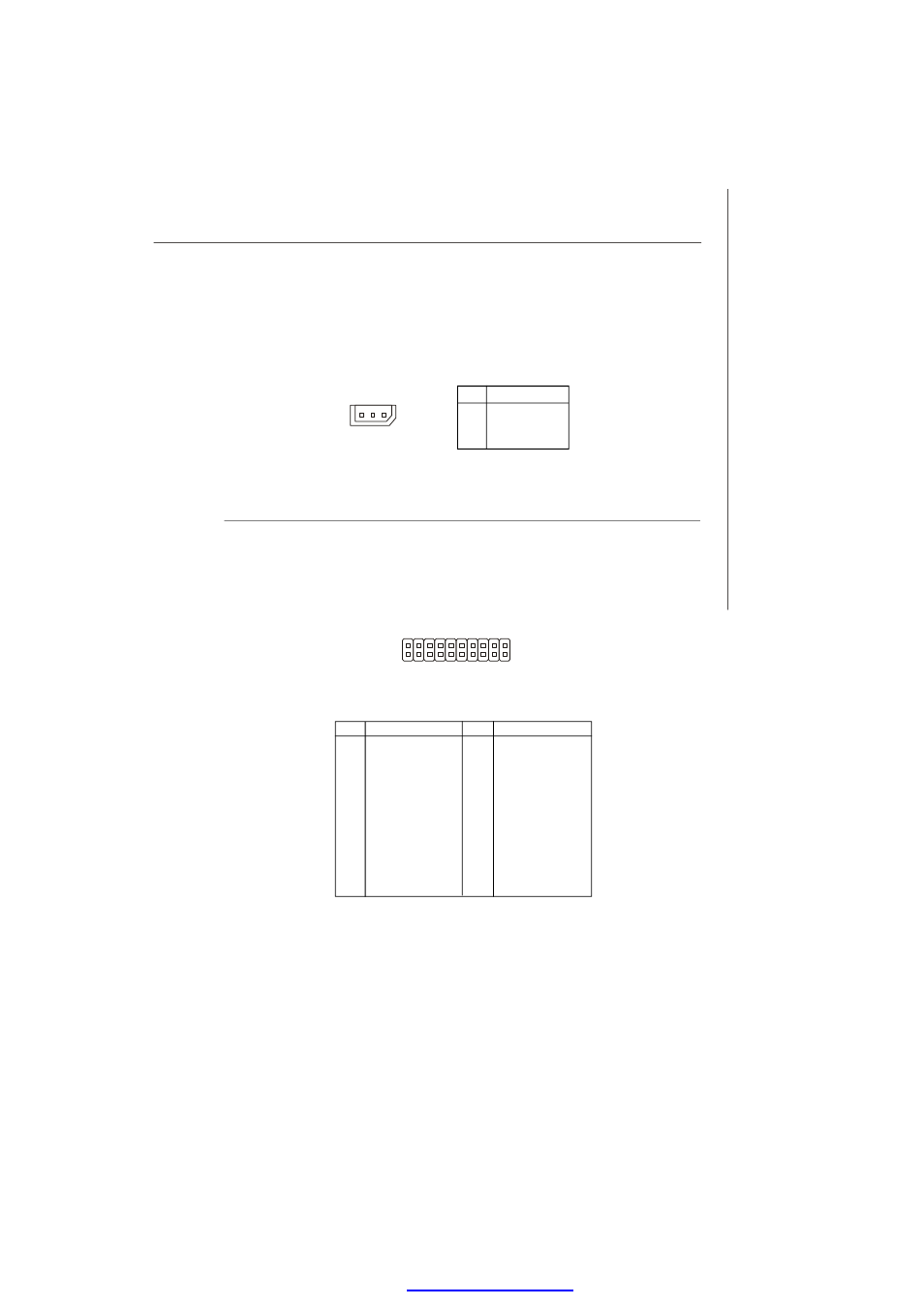
IPMB Connector: J_IPMB1
This connector is used to connect the IPMB (Intelligent Platform Management Bus)
SMBus.
Pin Definition
PIN
SIGNAL
1
IPMB_DATA
2
GND
3
IPMB_CLK
J_IPMB1
3
1
20
19
1
JFP1
2
PIN
SIGNAL
PIN
SIGNAL
1
Power LED+
2
Power LED-
3
SATA HDD LED+
4
SATA HDD LED-
5
LAN LED+
6
LAN LED-
7
ID LED+
8
ID LED-
9
Fault LED+
10
Fault LED-
11
Power+
12
Power-
13
Reset +
14
Reset-
15
ID+
16
ID-
17
I2C_Data
18
I2C_Clock
19
Chassis Intrusion+
20
Chassis Intrusion-
Pin Definition
PDF created with pdfFactory Pro trial versi
See also other documents in the category MSI Hardware:
- AM-690E (68 pages)
- IM-GM45 (73 pages)
- IM-GM45 (1 page)
- MS-7304 (52 pages)
- MS-6534 (109 pages)
- NVIDIA MS-7504PV (50 pages)
- G52-M6570XA-G22 (116 pages)
- RG300EX LITE (53 pages)
- MS-7242 (102 pages)
- CX700 (66 pages)
- GM965 (76 pages)
- G31M3 (96 pages)
- Fuzzy Mainboard GM965 (76 pages)
- 845 PRO2 (101 pages)
- FUZZY CX700 (82 pages)
- MS-7181 (107 pages)
- G45 (95 pages)
- FUZZY 945GM1 (83 pages)
- US54G (41 pages)
- MS-6566 (85 pages)
- MS-6380 (85 pages)
- MS-6575 (68 pages)
- IM-945GSE SERIES MS-9830 (83 pages)
- G52-S9617X1 (97 pages)
- G52-MA00628 (85 pages)
- MS-6523 (54 pages)
- ATX Motherboard G52-MA00362 (84 pages)
- N680GTX TWIN FROZR 4GD5/OC (1 page)
- N670 PE 2GD5/OC (1 page)
- N670GTX-PM2D2GD5/OC (1 page)
- N640GT-MD1GD3 (1 page)
- N630GT-MD4GD3 (1 page)
- N620GT-MD2GD3/LP (1 page)
- N610GT-MD2GD3/LP (1 page)
- N580GTX LIGHTNING XTREME EDITION (2 pages)
- N580GTX TWIN FROZR II/OC (2 pages)
- N560GTX-TI M2D1GD5/OC (2 pages)
- N560GTX-TI HAWK (2 pages)
- N560GTX-M2D1GD5 (2 pages)
- N460GTX-M2D1GD5/OC2 (2 pages)
- N460GTX HAWK TALON ATTACK (2 pages)
- N450GTS-MD1GD3 (2 pages)
- N440GT-MD1GD3/LP (2 pages)
- N430GT-MD1GD3/OC (2 pages)
- N220GT-MD1GD3/LP (2 pages)