3 packaged hardware, Packaged hardware, One set of 19-inch mounting brackets – ADC PowerWorx Power Distribution Products User Manual
Page 9
ADCP-80-545 • Issue 3 • March 2006
Page 3
© 2006, ADC Telecommunications, Inc.
The input power terminals, output power terminals, alarm terminals, and grounding studs are
mounted on the rear side of the panel enclosure. The plastic protective covers install over the
input and output power terminals. The covers prevent accidental contact with the terminals
when power is applied to the panel. The internal bus wiring and alarm relay circuit boards are
mounted within the enclosure and are not user accessible.
1.3
Packaged Hardware
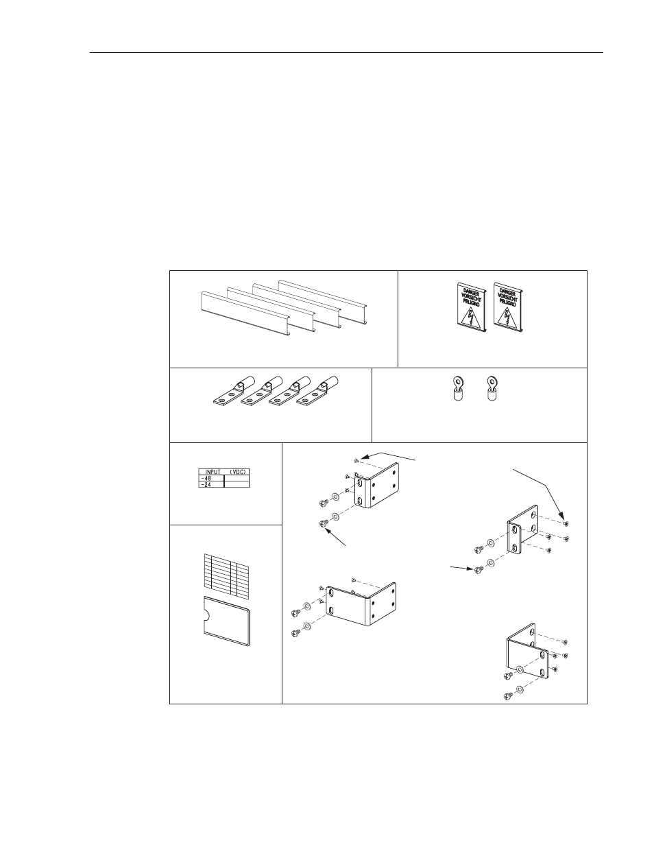
The Select Series circuit breaker panel includes various hardware components that are packaged
separately and shipped in the carton with the basic panel. The packaged hardware components
are shown in
and include the following items:
Figure 2. Packaged Hardware Components
• One set of 19-inch mounting brackets
ORIENTATION FOR
19-INCH RACK INSTALLATION
ORIENTATION FOR
23-INCH RACK INSTALLATION
3/8-INCH (9.525 MM) 12-24
SCREWS AND #12 WASHERS
5/16-INCH (7.936 MM) 8-32
FLAT-HEAD SCREWS
17942-A
UNIVERSAL MOUNTING BRACKETS
AND SCREWS
DESIGNATION CARD
AND CARD HOLDER
2-HOLE LUGS FOR
2 AWG WIRE
#10 RING TERMINALS FOR
12-10 AWG WIRE
REAR COVERS FOR OUTPUT
POWER/ALARM TERMINAL BLOCK
REAR COVERS FOR INPUT
POWER TERMINAL BLOCK
VOLTAGE
LABEL