Figure 18 – ADC PowerWorx Power Distribution Products User Manual
Page 32
ADCP-80-545 • Issue 3 • March 2006
Page 26
© 2006, ADC Telecommunications, Inc.
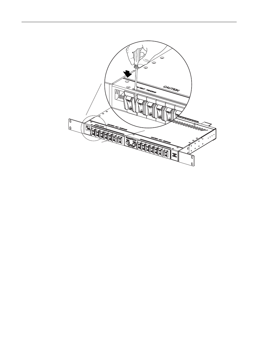
Figure 18. Releasing Circuit Breaker Lock Tab
2. Insert a flat-bladed screwdriver into the slot above the circuit breaker (see
).
3. Push down and forward on the upper circuit breaker lock tab until the top of the circuit
breaker is released from the panel.
4. Hold the top edge of the circuit breaker to keep the circuit breaker from snapping back into
the panel when the screwdriver is withdrawn from the slot.
5. Insert a flat-bladed screwdriver into the slot below the circuit breaker.
6. Push down and forward on the lower circuit breaker lock tab until the bottom of the circuit
breaker is released from the panel.
7. Pull the circuit breaker forward and out of the panel to expose the wiring connections on
the rear side of the circuit breaker.
8. Disconnect the power and load wires (large black and white wires) and the alarm wires
(small black wires) from the terminals on the rear side of the circuit breaker. Refer to
when replacing a single-pole breaker. Refer to
when replacing a two-
pole breaker.
9. Connect the power and load wires to the specified terminals on the rear side of the
replacement circuit breaker (see
). Note that with the circuit breaker
oriented as shown, the black load wire(s) connect to the top terminal(s) and the white
power wire(s) connect to the bottom (LINE) terminal(s).
17340-B
1.INSERT SCREWDRIVER
INTO SLOT AND DEPRESS
TO RELEASE LOCKING TAB
.
2.TILT BREAKER FORWARD.