6 input power connections, Input power connections – ADC PowerWorx Power Distribution Products User Manual
Page 24
ADCP-80-545 • Issue 3 • March 2006
Page 18
© 2006, ADC Telecommunications, Inc.
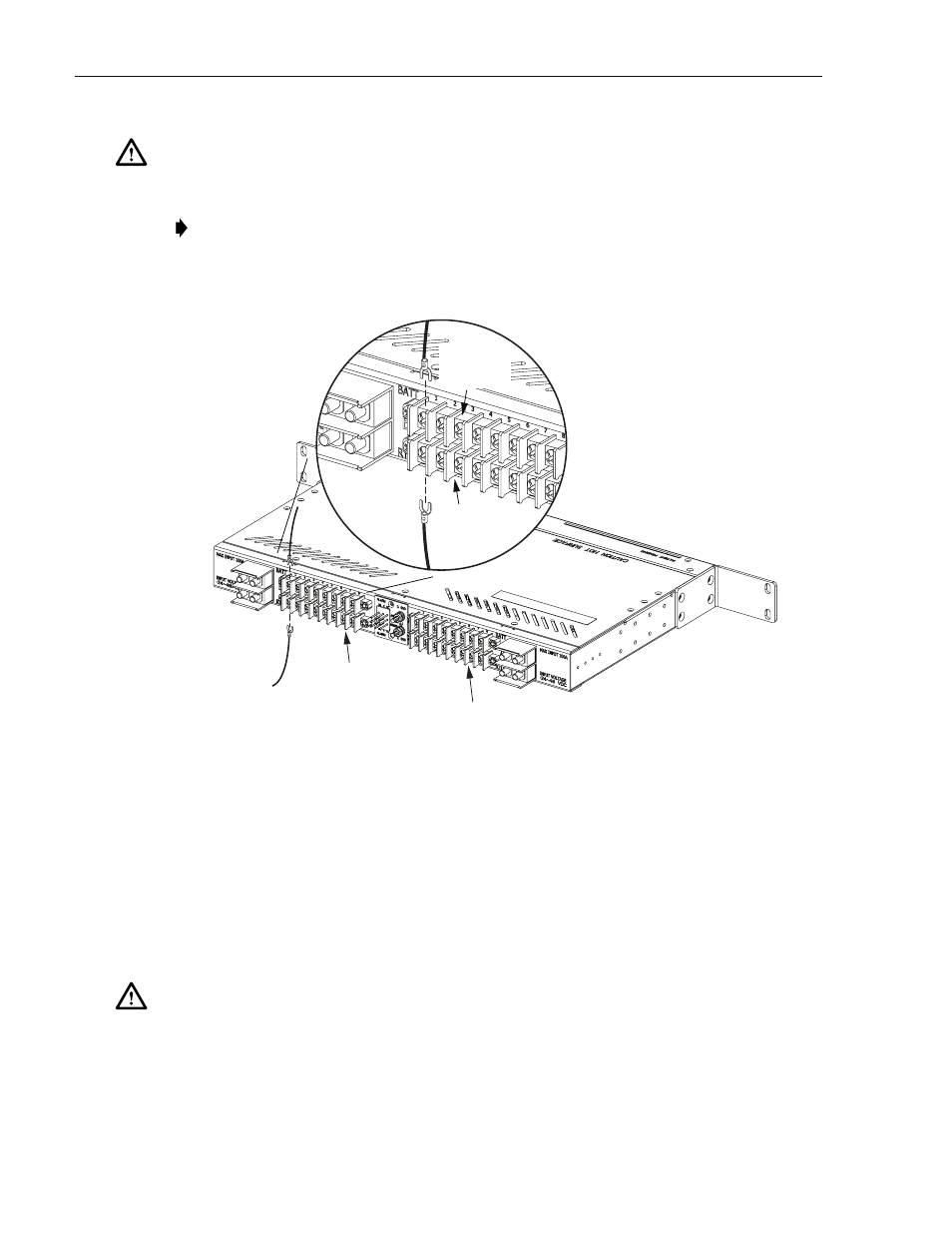
Figure 11. Output Power Connections
3.6
Input Power Connections
Input power is supplied to the circuit breaker panel through the A and B input terminal blocks.
Each input terminal block consists of two pairs of studs that are used for connecting the BATT
(battery –) and RTN (return +) input power cables. Each set of studs accepts various size 2-hole
compression lugs. Nuts (with captive locking washers) are provided to secure the compression
lugs to the studs.
Caution: Connecting the protected equipment to the wrong circuit may cause damage to the
equipment or the circuit breaker panel. Make sure the circuit breaker is the correct type and has
the correct current rating as specified by the protected equipment manufacturer.
Note: The continuous output load of the equipment during normal operation should not
exceed 80% of the rated value of the circuit breaker. This allows some room for
manufacturing tolerances and voltage fluctuations in the plant power mains.
Caution: Connect only the input voltage wire [the wire labeled BATTERY or BATT, or labeled
with the negative (–) voltage polarity and/or the voltage value] to the connector on the circuit
breaker panel labeled BATTERY. Connect only the input return wire [the wire labeled RTN,
RETURN, or BATTERY GROUND, or labeled with the positive (+) voltage polarity] to the
connector on the circuit breaker panel labeled RETURN.
17934-A
TIGHTEN TERMINAL SCREWS
TO 15 POUND-FORCE INCHES
(1.7 NEWTON METERS)
OF TORQUE
DETAIL DRAWING OF OUTPUT
TERMINAL BLOCK CONNECTIONS
POWER BUS B
OUTPUT TERMINALS
POWER BUS A
OUTPUT TERMINALS
POWER
RETURN
TERMINALS
POWER
FEED
TERMINALS