ADC PowerWorx Power Distribution Products User Manual
Page 19
ADCP-80-545 • Issue 3 • March 2006
Page 13
© 2006, ADC Telecommunications, Inc.
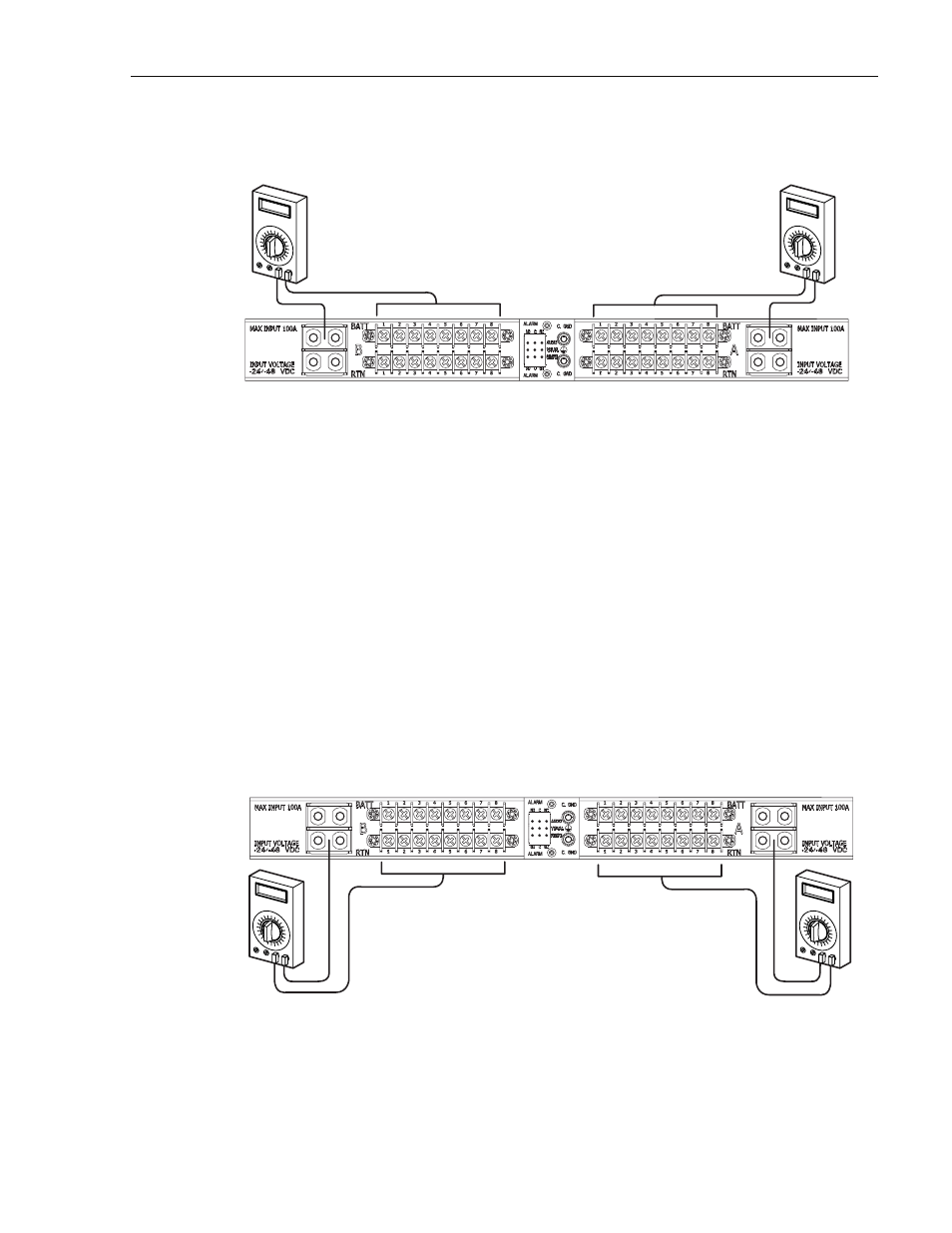
Figure 5. Test 2: Input Battery to Output Battery
Test 3: Input Return to Output Return - Connect one test probe to the A input power RTN
(+) terminal and the other test probe to the #1 output power RTN (+) terminal on the A output
terminal block (see
). Verify that continuity exists between the specified terminals.
Repeat the test procedure for each of the remaining output power RTN terminals. Repeat the
same test procedure for the B input power terminal block circuits.
Test 4: Alarm Terminals - Connect the test probes alternately between the C and NC terminals
and the C and NO terminals on each set of alarm terminals. Verify that no continuity exists
between the C and NC terminals and that continuity does exist between the C and NO terminals.
If the circuit breaker panel fails any of the specified tests, it is defective and must not be
installed. Contact ADC (see
Section 7, Customer Information and Assistance
) for an RMA
(Return Material Authorization) and to reorder if replacement is required.
Figure 6. Test 3: Input Return to Output Return
17945-A
TEST 2- POWER BUS B:
VERIFY CONTINUITY EXISTS
BETWEEN INPUT AND
OUTPUT BATT TERMINALS
TEST 2- POWER BUS A:
VERIFY CONTINUITY EXISTS
BETWEEN INPUT AND
OUTPUT BATT TERMINALS
17946-A
TEST 3- POWER BUS B:
VERIFY CONTINUITY EXISTS
BETWEEN INPUT AND
OUTPUT RTN TERMINALS
TEST 3- POWER BUS A:
VERIFY CONTINUITY EXISTS
BETWEEN INPUT AND
OUTPUT RTN TERMINALS