Figure 3. cdb5532u channel setup register window, Cdb5532u – Cirrus Logic CDB5532U User Manual
Page 8
CDB5532U
8
DS807DB1
Read Data: This button will instruct the ADC to begin performing repeated single (fully-settled) conver-
sions on the setup channel specified by the Setup Register box. The results of the most-recent conversion
are displayed in the Last Conversion box, as well as the Channel and Overflow indicators for each con-
version. The software will halt the data collection process when the user clicks the Stop button.
Configuration Register: In the Configuration Register box, the contents of the configuration register are
displayed, and can be modified by typing a hexadecimal value in the Hexadecimal: box, or by changing
any of the values below the Hexadecimal: box to the desired settings. Note: When changing the value of
the reset system bit to ‘1’ (RS, bit 29 in the configuration register), the part will be reset, and all registers
will return to their default values. It is a good idea to click the Update Registers button after performing a
reset to update the screen with the new register values.
Channel Setup Registers: In the Channel Setup Registers box, both channel setup registers are dis-
played in hexadecimal. These registers can be modified from the Channel Setup Register window, which
is accessed by selecting the Edit CSRs button.
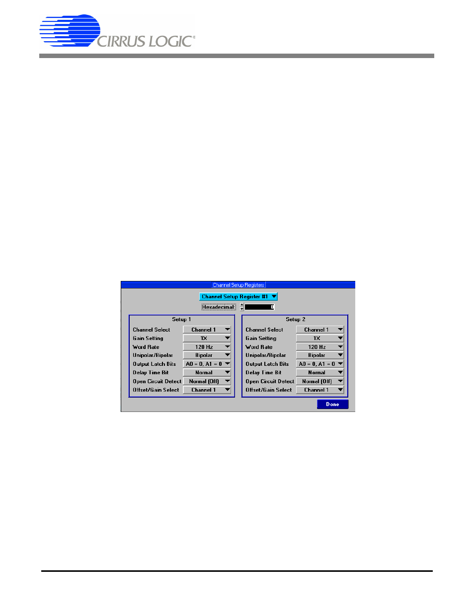
Channel Setup Register Window: In the Channel Setup Register window (Figure 3), each of the two
CSRs can be decoded and modified. The blue box at the top of the window allows the user to switch be-
tween CSRs. Each 32-bit CSR contains two 16-bit “Setups” which are decoded in the two boxes below
the hexadecimal value. The currently displayed CSR can be modified by either typing a value directly in
the Hexadecimal: box or by changing the decoded values in the individual setup boxes.
Figure 3. CDB5532U Channel Setup Register Window
Offset / Gain Registers: In the Offset / Gain Registers box, the offset and gain registers for all channels
are displayed in hexadecimal. These registers can all be modified in the Calibration window, which is ac-
cessed when the user selects the Calibration Window button.