Cirrus Logic CDB5528 User Manual
Preliminary product information, Features, General description
Preliminary Product Information
This document contains information for a new product.
Cirrus Logic reserves the right to modify this product without notice.
1
Copyright
Cirrus Logic, Inc. 2000
(All Rights Reserved)
P.O. Box 17847, Austin, Texas 78760
(512) 445 7222 FAX: (512) 445 7581
http://www.cirrus.com
\
CDB5521/22/23/24/28
CDB5521/22/23/24/28 Evaluation Board and Software
Features
l
Evaluation Board and Software Supports All
Chips: CS5521, CS5522, CS5523, CS5524,
and CS5528
l
Direct Thermocouple Interface
l
RS-232 to PC With Test Modes
l
On-board 80C51 Microcontroller
l
On-board Voltage Reference
l
Lab Windows/CVI
TM
Evaluation Software
– Register Setup & Chip Control
– Data Capture
– FFT Analysis
– Time Domain Analysis
– Noise Histogram Analysis
l
On-board Charge Pump Drive Circuitry
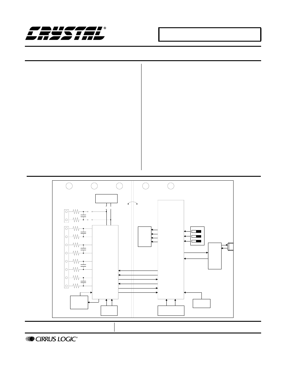
General Description
The CDB5521/22/23/24/28 is an inexpensive tool de-
signed to evaluate the performance of the CS5521,
CS5522, CS5523, CS5524, and CS5528 Analog-to-Dig-
ital Converters (ADC).
The evaluation board includes a 2.5 V voltage reference,
an 80C51 microcontroller, an RS232 driver/receiver, and
firmware. The 8051 controls the serial communication
between the evaluation board and the PC via the firm-
ware, thus, enabling quick and easy access to all of the
CS5521/22/23/24/28’s registers.
The CDB5521/22/23/24/28 also includes one installed
ADC sample, and software for Data Capture, Time Do-
main Analysis, Histogram Analysis, and Frequency
Domain Analysis.
ORDERING INFORMATION
CDB5521/22/23/24/28
Evaluation Board
AIN1+
AIN1-
AIN2+
AIN2-
AIN3+
AIN3-
AIN4+
AIN4-
NBV
CPD
NBV DRIVE
CIRCUITRY
CRYSTAL
32.768 kHz
REF+
REF-
VOLTAGE
REFERENCE
J2
+5 ANALOG
-5 ANALOG
AGND
CS5522
CS5523
CS5524
CS5528
+5 DIGITAL
DGND
LEDs
A1
A0
SCLK
SDO
SDI
CS
80C51
Microcontroller
TEST
SWITCHES
CRYSTAL
11.0592 MHz
RESET
CIRCUITRY
RS232
DRIVER/RECEIVER
RS232
CONNECTOR
J1
3
2
1
on off
CS5521
MAY ‘00
DS317DB2
Document Outline
- CDB5521/22/23/24/28
- 1. Part I: Hardware
- 1.1 Introduction
- 1.2 Evaluation Board Overview
- 1.3 Using the Evaluation Board
- 1.4. Power Connections
- 1.5 Negative Bias Voltage
- 1.6 Software
- 1.7. Writing Your Own Interface Software
- Table 1. Header Descriptions
- Table 2. Microcontroller Read/Write Commands via RS-232
- Table 3. Microcontroller Conversion Commands via RS-232
- Table 4. Microcontroller Self Calibration Commands via RS-232
- Table 5. Microcontroller System Calibration Commands via RS-232
- 2. Part II: Software
- 2.1 Installation Procedure
- 2.2 Using the Software
- 2.3 Menu Bars Overview
- 2.4 Setup Window Overview
- 2.5 Data FIFO Window Overview
- 2.6 Histogram Window Overview
- 2.7 Frequency Domain Window (i.e. FFT)
- 2.8 Time Domain Window Overview
- 2.9 Calibration Window Overview
- 2.10 Trouble Shooting the Evaluation Board
- Figure 5. Main Menu
- Figure 6. Setup Window
- Figure 7. Data FIFO Window
- Figure 8. Frequency Domain Analysis
- Figure 9. Calibration Menu
- Figure 10. Time Domain Analysis
- Figure 11. Histogram Analysis (Using the CS5524 with default register settings and 24-bit output ...
- Figure 12. CDB5521/22/23/24/28 Component Side Silkscreen
- Figure 13. CDB5521/22/23/24/28 Component Side (top)
- Figure 14. CDB5521/22/23/24/28 Solder Side (bottom)