An152 – Cirrus Logic AN152 User Manual
Page 4
AN152
4
AN152REV1
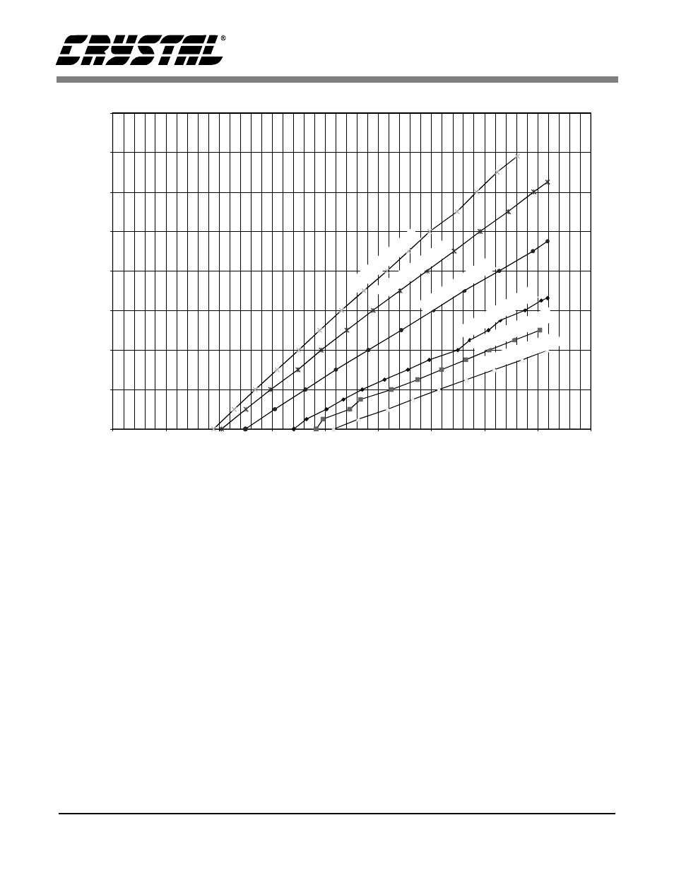
plot shows that if the charge pump output has no
external load, its average output frequency (VA+ =
5 V, C =0.033 uF) is approximately 8 kHz which is
about ½ the maximum possible output frequency.
The charge pump runs at this average frequency to
support the load of the on-chip instrumentation am-
plifier.
Figure 7 illustrates load current vs. CPD frequency
for the CS5525/26 devices. The charge pump clock
(CPCLK) is derived from XIN (set to 32.768 kHz),
therefore the maximum frequency which can be
output from CPD is equal to XIN.
The plots show data similar to that in figure 6. Be-
cause the charge pump frequency in the CS5525/26
devices is twice as fast as that used in the
CS5521/22/23/24/28 devices, the charge pump ca-
pacitor is ½ the size (for the same XIN clock fre-
quency).
Figure 8 illustrates the CS5521/22/23/24/28 with
the charge pump capacitor increased to 0.15
µ
F.
This charge pump capacitor is about 4.5 times larg-
er than the nominal capacitor. Under this condition
the charge pump could readily supply 2 mA to an
external load. While the plot indicates that 3 mA
can be supplied, it is not recommended that the ex-
ternal load exceed 2 mA. This allows for some
margin in the design. The actual maximum output
load capability is affected by the tolerances of
VA+, VD+, and the tolerance limits of the charge
pump capacitor.
Figures 9 and 10 illustrate the CS5521/22/23/24/28
running with a VD+ supply of 3 V. Figure 9 indi-
cates the variation in load current capability when
VA+ varies from 4.5 to 5.5 V (VD+ =3.0 V). Fig-
ure 10 illustrates the variation in load capability
when VA+ is a constant 5.0 V, but VD+ is varied
0
200
400
600
800
1000
1200
1400
1600
0.00
2.00
4.00
6.00
8.00
10.00
12.00
14.00
16.00
18.00
Frequency (KHz)
L
o
a
d
C
u
rren
t (
u
A
)
0.0
33
uF
@
5.
5 V
0.0
68
uF
@
4
.5
V
0.0
33
uF
@
5.0
V
0.03
3 uF
@
4.5
V
0.
06
8
uF
@
5
.5
V
0.
06
8
uF
@
5
.0
V
(µA
)
Figure 6. Load Current vs. Frequency for the CS5521/23 and CS5522/24/28; VA+ = VD+