1 main program loop, Figure 2. software flow diagram, 2 initialize – Cirrus Logic AN118 User Manual
Page 2: 1 main program loop 3.2 initialize, An118
AN118
2
AN118REV2
80C51 assembly language, providing a good set of
tools for both C and assembly programmers to
build their own designs upon. While reading this
application note, please refer to Section 7. “Appen-
dix: 80C51 Microcontroller Code” on page 9 for
the code listing.
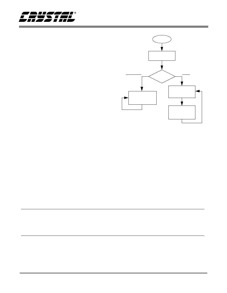
3.1 Main Program Loop
The main loop of the program is responsible for
calling all other algorithms and controlling the pro-
gram flow. Figure 2 depicts the data flow of the
main loop. When the evaluation board is first pow-
ered up, or after a system reset, the microcontroller
and ADC are set up by calling the initialize routine.
The value present on the DIP switches is then
checked. If this value is anything other than zero,
the program goes into test mode. If the value is
equal to zero, the program goes into a continuous
loop, where it receives commands from the PC, de-
codes them, and performs the desired actions.
3.2 Initialize
Initialize is used to configure the microcontroller
and the ADC to the proper settings that will allow
the PC to control the ADC indirectly through the
microcontroller. The 80C51’s port P1 is configured
as depicted in Figure 1 (for more information on
configuring ports refer to the 80C51 Data Sheet).
Next, port P2 is written twice, once with all zeros
and once with all ones, with a delay in between to
control the LEDs attached to the port and inform
the user that the board has been reset successfully.
Port P3 is then set up to use the 80C51’s internal
UART to interface to the PC at 9600 baud, no par-
ity bit, eight data bits, and one stop bit. To allow
time for the ADCs oscillator to start up, a delay
state is entered (oscillator start-up time is typically
500ms). After this delay, the ADC is ready to ac-
cept data. However, it is a good idea to reset the
ADC’s serial port before communicating with it.
To reset the serial port on the ADC, SDI is asserted,
and 255 SCLKs are provided. SDI is then cleared,
and one final SCLK is provided (this is a slight
overkill, as only 15 bytes of logic 1’s followed by a
Contacting Cirrus Logic Support
For a complete listing of Direct Sales, Distributor, and Sales Representative contacts, visit the Cirrus Logic web site at:
http://www.cirrus.com/corporate/contacts/
SPI is a trademark of Motorola.
MICROWIRE is a trademark of National Semiconductor.
Cirrus Logic, Inc. has made best efforts to ensure that the information contained in this document is accurate and reliable. However, the information
is subject to change without notice and is provided “AS IS” without warranty of any kind (express or implied). No responsibility is assumed by Cirrus
Logic, Inc. for the use of this information, nor for infringements of patents or other rights of third parties. This document is the property of Cirrus
Logic, Inc. and implies no license under patents, copyrights, trademarks, or trade secrets. No part of this publication may be copied, reproduced,
stored in a retrieval system, or transmitted, in any form or by any means (electronic, mechanical, photographic, or otherwise). Furthermore, no part
of this publication may be used as a basis for manufacture or sale of any items without the prior written consent of Cirrus Logic, Inc. The names of
products of Cirrus Logic, Inc. or other vendors and suppliers appearing in this document may be trademarks or service marks of their respective
owners which may be registered in some jurisdictions. A list of Cirrus Logic, Inc. trademarks and service marks can be found at http://www.cir-
rus.com.
START
INITIALIZE
CHECK
DIPS
TEST MODES
DECODE
COMMAND
Zero
Non-Zero
GET
COMMAND
Figure 2. Software Flow Diagram