Basic application circuits, Figure 14. typical connection diagram, Figure 14 – Cirrus Logic CS5464 User Manual
Page 42: Cs5464
CS5464
42
DS682F3
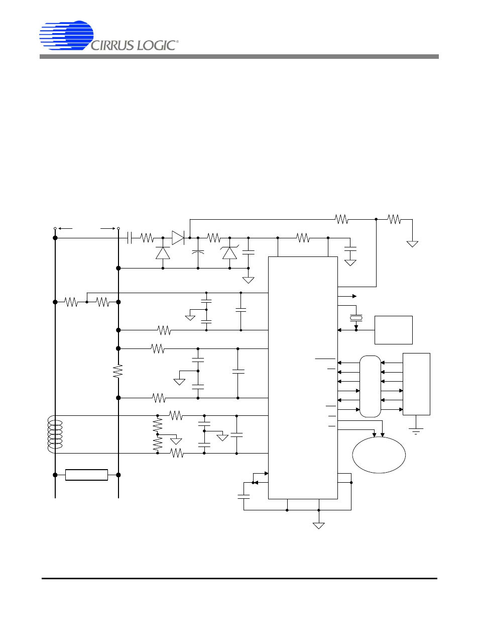
11. BASIC APPLICATION CIRCUITS
shows the CS5464 configured to measure
power in a single-phase, 2-wire system while operating
in a single-supply configuration. In this diagram, a shunt
resistor is used to sense the line current and a voltage
divider is used to sense the line voltage. In this type of
shunt-resistor configuration, the common-mode level of
the CS5464 must be referenced to the line side of the
power line. This means that the common-mode poten-
tial of the CS5464 will track the high-voltage levels, as
well as low-voltage levels, with respect to earth ground.
Isolation circuitry is required when an earth-ground-ref-
erenced communication interface is connected. A cur-
rent transformer (CT) is connected to the return line
current, which implements the tamper detection circuit.
VA+
VD+
CS5464
0.1µF
470µF
500 W
1uF
500
L2
R
1
R
2
10W
9
IIN-
10
19
20
IIN+
PFMON
CPUCLK
XOUT
XIN
Optional
Clock
Source
Serial
Data
Interface
RESET
2
1
CS
7
SDI
27
SDO
6
SCLK
5
INT
24
E1
0.1µF
VREFIN
12
VREFOUT
11
AGND
DGND
17
4
3
4.096 MHz
0.1 µF
10 kW
5 kW
L1
R
Shunt
R
V-
R
I-
R
I+
ISOLAT
IO
N
(Optional)
Pulse Output
Counter
26
25
C
I-
C
I+
C
Idiff
C
V+
C
V-
C
Vdiff
E2
IIN2-
IIN2+
½ R
R
I-
R
I+
C
Burden
Idiff
15
16
18
21
28
23
VIN-
VIN+
TEST2
13
14
TEST1
LOAD
LINE
VOLTAGE
CT
½ R
Burden
C
I-
C
I+
W
Figure 14. Typical Connection Diagram (Single-phase, 2-wire – Direct Connect to Power Line)