Table 2. clock and data formatting options, Figure 6. clock and data header connections, j4, 4 system status indicators – Cirrus Logic CRD5381 User Manual
Page 10: 5 system reset, 4 system status indicators 2.5 system reset, Figure 6, Crd5381
10
DS563RD1
CRD5381
indicates the jumper options for J8 with the associated output data formats and some common
clock frequencies.
.
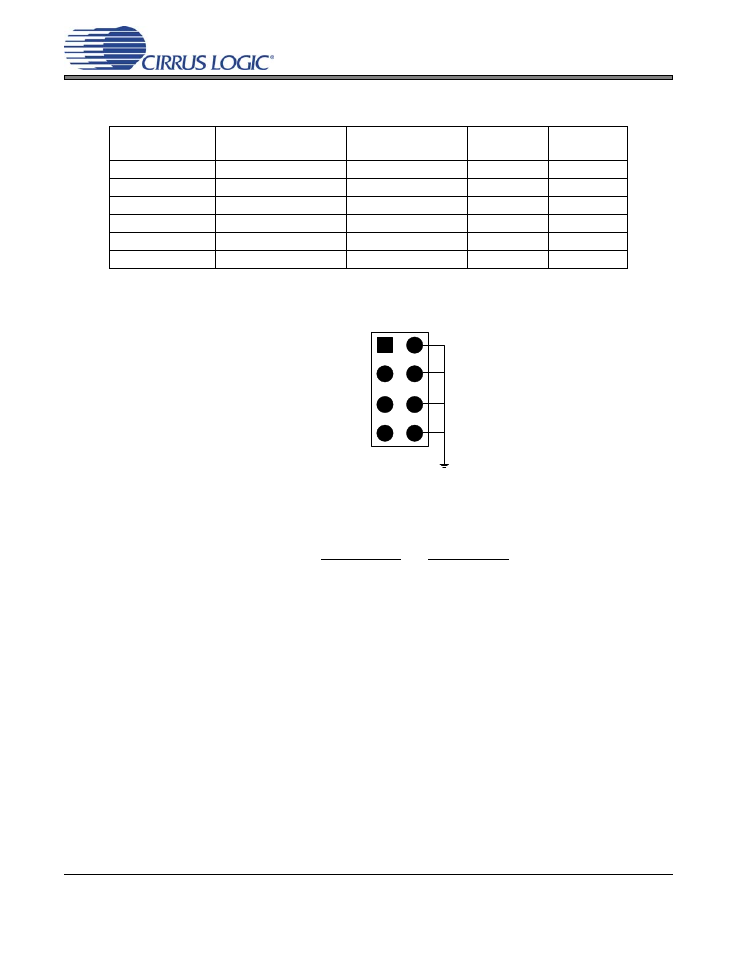
Figure 6. Clock and Data Header Connections, J4
2.4
System Status Indicators
ADC Overflow - Overflow indicators are provided for each CS5381. Overflow is indicated by the LED la-
beled ADC OVERFLOW A (D4) or ADC OVERFLOW B (D5) being lit. These control signals are also avail-
able as outputs on header J16, labeled OVERFLOW A and OVERFLOW B as shown in
.
SRC Unlock - SRC unlock indicators are provided for each CS8421. SRC unlock is indicated by the LED
labeled SRC UNLOCK A (D3) or SRC UNLOCK B (D2) being lit. These control signals are also available
as outputs on header J16, labeled SRC UNLOCK A and SRC UNLOCK B as shown in
2.5
System Reset
The CRD5381 provides an on-board reset and a connection for a user-applied reset signal through header
J16.
On-board Reset - The on-board reset signal is activated either upon power-up or by pressing push-button
S1. The reset signal is active-low, and is held low for approximately 350 ms after S1 has been pressed, or
power has been applied to the CRD5381.
External Reset - A connection is provided for a user to apply an external reset to the CRD5381 through
header J16 as shown in
. The external reset should be an active-low, +3.3 V signal.
When an external reset signal is connected to the CRD5381, the on-board reset is the logical OR of the
power-up reset, the push-button reset, and the external reset.
J8
SDOUTA Data Format
TDM/SDOUTB Data
Format
LRCK INPUT
Frequency
SCLK INPUT
Frequency
LJ
24-bit Left-Justified
24-bit Left-Justified
48 kHz
3.072 MHz
LJ
24-bit Left-Justified
24-bit Left-Justified
96 kHz
6.144 MHz
LJ
24-bit Left-Justified
24-bit Left-Justified
192 kHz
12.288 MHz
TDM
-
4-Channel TDM
48 kHz
6.144 MHz
TDM
-
4-Channel TDM
96 kHz
12.288 MHz
TDM
-
4-Channel TDM
192 kHz
24.576 MHz
Table 2. Clock and Data Formatting Options
LRCK INPUT
SCLK INPUT
SDOUT A
TDM/SDOUT B
Signal
Ground
J4