3 master clock, Table 3. master clock (mclk) ratios, 3 serial audio interface – Cirrus Logic CS5340 User Manual
Page 17: Figure 19. i·s serial audio interface, Figure 20. left-justified serial audio interface
DS601F2
17
CS5340
Confidential Draft
3/11/08
4.2.3
Master Clock
The CS5340 requires a Master clock (MCLK) which runs the internal sampling circuits and digital filters.
There is also an internal MCLK divider which is automatically activated based on the speed mode and
frequency of the MCLK.
shows a listing of the external MCLK/LRCK ratios that are required.
lists some common audio output sample rates and the required MCLK frequency. Please note
that not all of the listed sample rates are supported when operating with a fast MCLK (512x, 256x, 128x
for Single-, Double-, and Quad-Speed Modes, respectively).
4.3
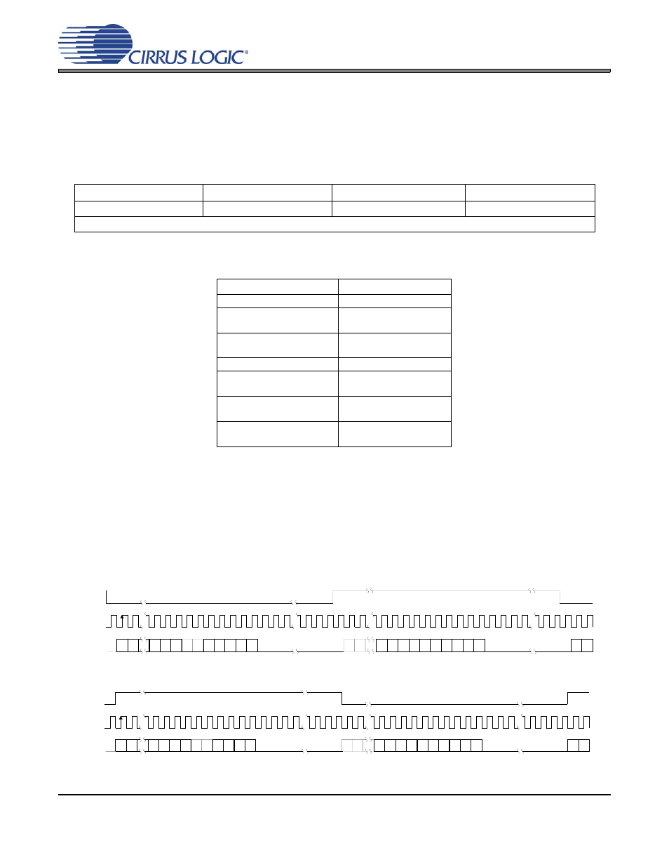
Serial Audio Interface
The CS5340 supports both I²S and Left-Justified serial audio formats. Upon start-up, the CS5340 will detect
the logic level on SDOUT (pin 4). A 10 k
Ω pull-up to VL is needed to select I²S format, and a 10 kΩ pull-
down to GND is needed to select Left-Justified format.
and
illustrate the I²S and Left-Justified
audio formats. Please see
, for more information on the required timing for the two
serial audio interface formats. Also see Application Note AN282 for a detailed discussion of the serial audio
interface formats.
Single-Speed Mode
Double-Speed Mode
Quad-Speed Mode
MCLK/LRCK Ratio
256x, 512x
128x, 256x
64x*,128x
* Quad Speed, 64x only available in Master Mode.
Table 3. Master Clock (MCLK) Ratios
SAMPLE RATE (kHz)
MCLK (MHz)
32
8.192
44.1
11.2896
22.5792
48
12.288
24.576
64
8.192
88.2
11.2896
22.5792
96
12.288
24.576
192
12.288
24.576
Table 4. Master Clock (MCLK) Frequencies for Standard Audio Sample Rates
S D A T A
2 3 2 2
8
7
2 3 2 2
S C LK
LR C K
2 3 2 2
6
5
4
3
2
1
0
8
7
6
5
4
3
2
1
0
9
9
L e ft C h a n n e l
R ig h t C h a n n e l
Figure 19. I²S Serial Audio Interface
S D A T A
2 3 2 2
7
6
2 3 2 2
S C L K
L R C K
2 3 2 2
5
4
3
2
1
0
8
7
6
5
4
3
2
1
0
8
9
9
L e ft C h a n n e l
R ig h t C h a n n e l
Figure 20. Left-Justified Serial Audio Interface