1 system block, 2 changing the audio input source, 1 audio in via s/pdif – Cirrus Logic CDB48500-USB User Manual
Page 24: 1 audio in via s/pdif -3, Figure 4-2. system configuration -2
2
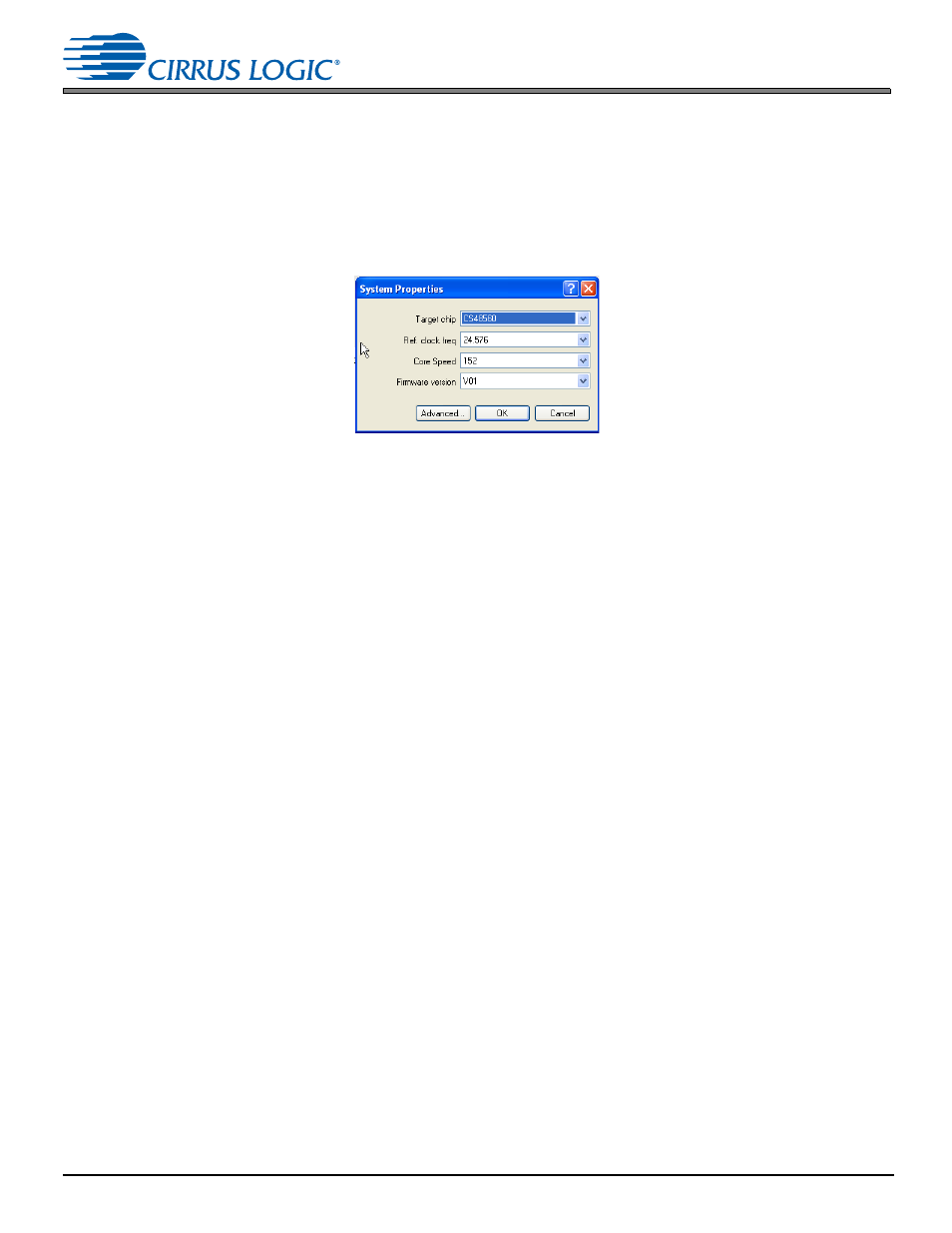
4.2.1 System Block
The CDB48500 board is populated with a CS48560. However it is possible to evaluate the CS48520, CS48540,
CS48560, CS485AU2B, and CS485DV2B on this board. When you drag the system block on to the work space,
a popup menu is displayed as shown in
. This menu lets you choose the target chip that you need to
evaluate. When you select the target chip, place the template of the target chip on the analog connectors. The
template is a guide that shows which input/output channels are valid for the selected chip.
.
Figure 4-2. System Configuration
4.2.2 Changing the Audio Input Source
The audio input to the DSP is selected through the “Audio In” block in DSP Composer. The Audio can be
delivered to the DSP via the following:
•
S/PDIF (J100 on S/PDIF)
•
Analog (J100 on 12CH_ADC)
•
Analog (J100 on 8CH_ADC)
•
Analog (J100 on 2CH_ADC)
•
USB (IIS)
•
Echo Audio
4.2.2.1 Audio In via S/PDIF
To deliver data to the DSP via S/PDIF, drag the Audio In block to the work space and select “SPDIF” as the Input
Source. Double click the Audio In block to see the signal flow. Right Click on SPDIF Rx. The device properties of
the S/PDIF IN element lets you select if the SPDIF input is on SPDIF_RXP (Optical In) or on SPDIF_RXN
(Coaxial). The Input FS depends on input stream and must not be changed. The Master/Slave property must
always be set to Master to indicate that the S/PDIF transmitter masters MCLK, SCLK and LRCLK as described
in
Section 3.1.11.2, “Clock and Data Flow for S/PDIF Input” on page 1-7
. The Audio In module with S/PDIF In as
the input source is shown in
.