4 configuring the cdb48500, 1 introduction, Chapter 4. configuring the cdb48500 -1 – Cirrus Logic CDB48500-USB User Manual
Page 23
1
Chapter 4
Configuring the CDB48500
4.1 Introduction
The DSP Composer™ software is a graphical user interface (GUI) that is used to program the CS485XX DSP,
and to configure the CDB48500. With the exception of the power selection and DAI input jumpers, the
CDB48500 is configured exclusively through software. This section provides basic instruction for using the GUI
to control the CDB48500, but detailed information can be found in the DSP Composer™ User’s Manual. Both
the DSP Composer™ software, and the User’s Manual for the software package will be provided by your local
Cirrus Logic representative.
4.2 Basic Application Download and System Configuration for PCM
Pass-through
Follow the instructions in
Chapter 1, "Board Setup and Installing the Evaluation Kit Software"
in order to install
the USB drivers on your PC and launch DSP Composer (the GUI used to control the CDB48500).
After following the instructions in
Section 2.1.4, “Running a Stereo PCM Application on CDB48500-USB” on
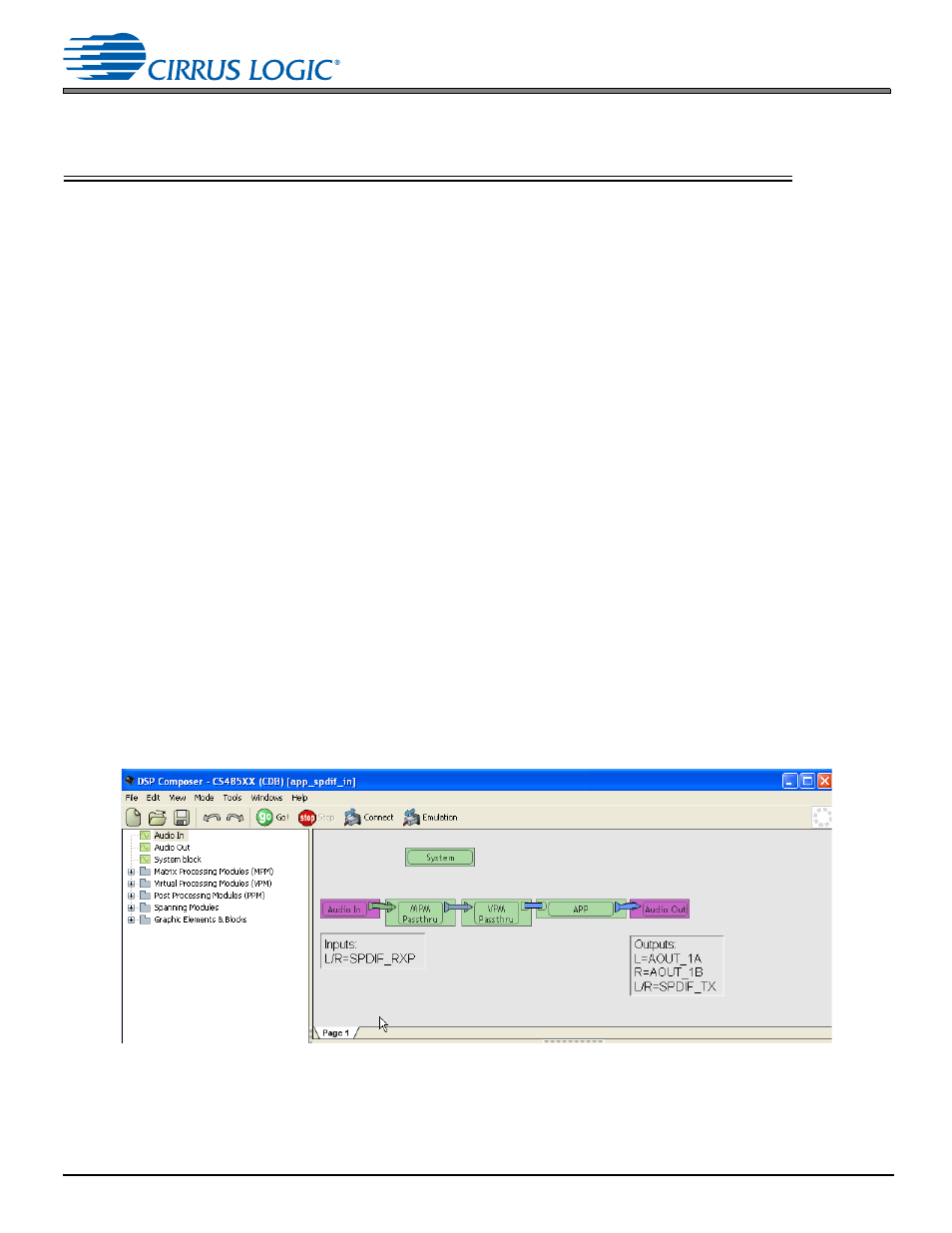
, the DSP Composer main window will appear as shown in
shows the DSP Composer™ main window for a PCM pass-through application on the CDB48500. The
blocks shown in the main window of DSP Composer™ can be selected from the folders in the left-hand window
pane, and then connected together by “wires” to indicate the processing path as shown.
The “Audio In” and “Audio Out” blocks represent the hardware ports that need to be configured. The “Audio In”
block is used to select the S/PDIF Input, Analog input or USB input that is to be processed. It configures the
digital audio format for the CS8416, ADC side of CS42448 and the DAI port of the CS485XX. The “Audio Out”
block is used to configure the digital audio format for the DAC side of the CS42448, the DAO port of the
CS485XX and enables or disables the S/PDIF TX output port of the CS485XX.
Figure 4-1. PCM Pass-through Example Application