Cirrus Logic CS4373A User Manual
Cs4373a low-power, high-performance, Test dac, Features
Copyright
© Cirrus Logic, Inc. 2006
(All Rights Reserved)
CS4373A
Low-power, High-performance
∆Σ
Test DAC
Features
z
Digital
∆Σ Input from CS5376A Digital Filter
z
Selectable Differential Analog Outputs
• Precision output (
OUT±
) for electronics tests
• Buffered output (
BUF±
) for sensor tests
z
Multiple AC and DC Operational Modes
• Signal bandwidth: DC to 100 Hz
• Max AC amplitude: 5 V
PP
differential
• Max DC amplitude: + 2.5 V
dc
differential
z
Selectable Attenuation for
CS3301A / CS3302A
• 1, 1/2, 1/4, 1/8, 1/16, 1/32, 1/64
z
Outstanding Performance
• AC (OUT): -116 dB THD typical, -112 dB max
• AC (BUF): -108 dB THD typical, -90 dB max
• DC absolute accuracy: 0.4% typical, 1% max
z
Low Power Consumption
• AC modes / DC modes: 40 mW / 20 mW
• Sleep mode / Power Down: 1 mW / 10
µW
z
Extremely Small Footprint
• 28-pin SSOP package, 8 mm x 10 mm
z
Bipolar Power Supply Configuration
• VA+ = +2.5 V;VA- = -2.5 V; VD = +3.3 V
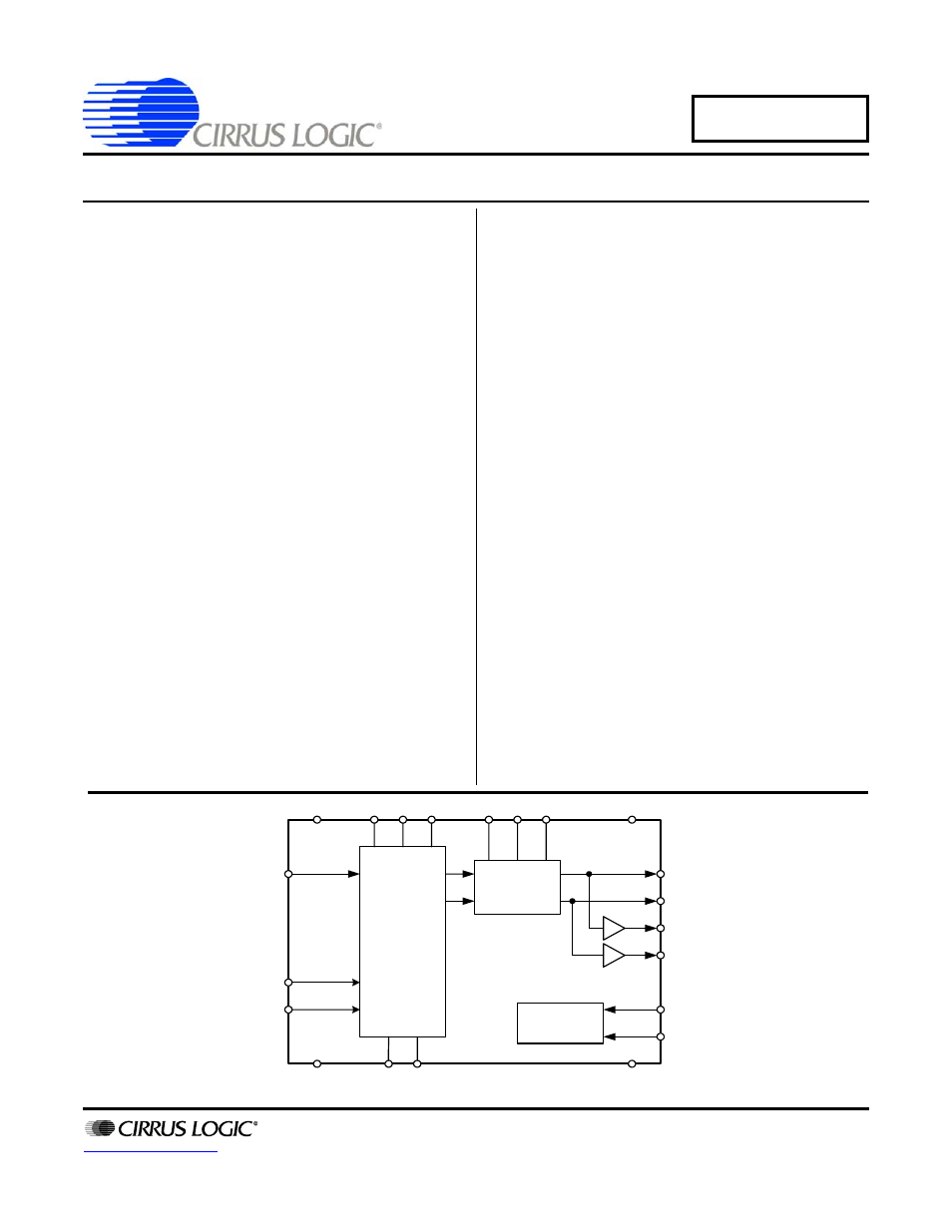
Description
The CS4373A is a high-performance, differential output
digital-to-analog converter (DAC) with programmable at-
tenuation and multiple operational modes. AC test
modes measure system dynamic performance through
THD and CMRR tests while DC test modes are for gain
calibration and pulse tests.
The CS4373A is driven by a
∆Σ digital bit stream from the
CS5376A digital filter test bit stream (TBS) generator. It
has two sets of differential analog outputs, OUT and
BUF, to simplify system design as dedicated outputs for
testing the electronics channel and for in-circuit sensor
tests. Analog output attenuation is selected by simple pin
settings and matches the gain of the
CS3301A / CS3302A differential amplifiers for full-scale
testing at all gain ranges.
The CS4373A test DAC provides self-test and precision
calibration capability for high-resolution, low-frequency
multi-channel measurement systems designed from
CS3301A / CS3302A differential amplifiers,
CS5371A / CS5372A
∆Σ modulators and the CS5376A
digital filter.
ORDERING INFORMATION
See
24-Bit
∆Σ
DAC
Attenuator
Clock
Generator
TDATA
VA+
MODE(0, 1, 2)
ATT(0, 1, 2)
VD
VA-
VREF+
VREF-
GND
OUT+
OUT-
BUF+
BUF-
CAP+ CAP-
MCLK
MSYNC
DEC ‘06
DS699F2
Document Outline
- Table of Contents
- List of Figures
- List of Tables
- 1. CharacteristicsandSpecifications
- 2. General Description
- 3. System Diagrams
- 4. Power Modes
- 5. Operational Modes
- 6. Digital Inputs
- 7. Analog Outputs
- 8. Voltage Reference
- 9. Power Supplies
- 10. Terminology
- 11. Pin Description
- 12. Package Dimensions
- 13. Ordering Information
- 14. Environmental, Manufacturing, & Handling Information
- 15. Revision History