2 mode select, Table 5. mode selection, hardware mode options, Cs4364 – Cirrus Logic CS4364 User Manual
Page 21
DS619F1
21
CS4364
4.2
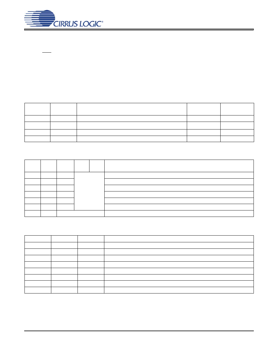
Mode Select
In Hardware Mode, operation is determined by the Mode Select pins. The states of these pins are continu-
ally scanned for any changes; however, the mode should only be changed while the device is in reset
(RST pin low) to ensure proper switching from one mode to another. These pins require connection to sup-
ply or ground as outlined in
. For M0, M1, and M2, supply is VLC. For M3 and M4, supply is VLS.
show the decode of these pins.
In Software Mode, the operational mode and data format are set in the FM and DIF registers. See
Control (Address 03h)” on page 34
M1
(DIF1)
M0
(DIF0)
DESCRIPTION
FORMAT
FIGURE
0
0
Left Justified, up to 24-bit data
0
0
1
I
2
S, up to 24-bit data
1
1
0
Right Justified, 16-bit Data
2
1
1
Right Justified, 24-bit Data
3
Table 4. PCM Digital Interface Format, Hardware Mode Options
M4
M3
M2
(DEM)
M1
M0
DESCRIPTION
0
0
0
Single-Speed without De-Emphasis (4 kHz to 50 kHz sample rates)
0
0
1
Single-Speed with 44.1 kHz De-Emphasis; see
0
1
0
Double-Speed (50 kHz to 100 kHz sample rates)
0
1
1
Quad-Speed (100 kHz to 200 kHz sample rates)
1
0
0
Auto Speed-Mode Detect (32 kHz to 200 kHz sample rates)
1
0
1
Auto Speed-Mode Detect with 44.1 kHz De-Emphasis; see
1
1
DSD Processor Mode
Table 5. Mode Selection, Hardware Mode Options
M2
M1
M0
DESCRIPTION
0
0
0
64x oversampled DSD data with a 4x MCLK to DSD data rate
0
0
1
64x oversampled DSD data with a 6x MCLK to DSD data rate
0
1
0
64x oversampled DSD data with a 8x MCLK to DSD data rate
0
1
1
64x oversampled DSD data with a 12x MCLK to DSD data rate
1
0
0
128x oversampled DSD data with a 2x MCLK to DSD data rate
1
0
1
128x oversampled DSD data with a 3x MCLK to DSD data rate
1
1
0
128x oversampled DSD data with a 4x MCLK to DSD data rate
1
1
1
128x oversampled DSD data with a 6x MCLK to DSD data rate
Table 6. Direct Stream Digital (DSD), Hardware Mode Options