6 dac mute2 control, 7 dac de-emphasis control, 8 digital volume control – Cirrus Logic CS4228A User Manual
Page 24: Cs4228a
CS4228A
24
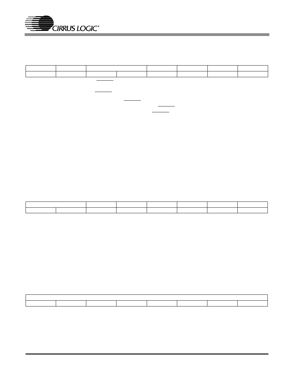
5.6
DAC Mute2 Control
Address 0x05
MUTEC
Controls the MUTEC pin
0 -
Normal operation
*1 -
MUTEC pin asserted low
MUTCZ
Automatically asserts the MUTEC pin on consecutive zeros. When enabled, 512 consecutive
zeros on all six DAC inputs will cause the MUTEC pin to be asserted low. A single non-zero
value on any DAC input will cause the MUTEC pin to deassert.
*0 -
Disabled
1 -
Enabled
HMUTE56/34/12
Hard mute the corresponding DAC pair. When asserted, zero data is sent to the corresponding
DAC pair causing an instantaneous mute. To prevent high frequency transients on the outputs,
a DAC pair should be fully attenuated by asserting the corresponding MUT6-MUT1 bits in the
DAC Mute Control register or by writing 0xFF to the corresponding Digital Volume Control reg-
isters before asserting HMUTE.
*0 -
Normal operation
1 -
DAC pair is muted
5.7
DAC De-emphasis Control
Address 0x06
DEMS1:0
Selects the DAC de-emphasis response curve.
0 -
Reserved
1 -
De-emphasis for 48 kHz
*2 -
De-emphasis for 44.1 kHz
3 -
De-emphasis for 32 kHz
DEM6 - DEM1
De-emphasis control for DAC6 - DAC1 respectively
*0 -
De-emphasis off
1 -
De-emphasis on
5.8
Digital Volume Control
Addresses 0x07, 0x08, 0x09, 0x0A, 0x0B, 0x0C
VOL6 - VOL1
Address 0x0C - 0x07 sets the attenuation level for DAC 6 - DAC1 respectively. The attenutation
level is ramped up and down at the rate specified by RMP1:0 in the DAC Volume Control Setup
register.
0 - 181 represents 0 to 90.5 dB of attenuation in 0.5 dB steps.
7
6
5
4
3
2
1
0
MUTEC
MUTCZ
RESERVED
HMUTE56
HMUTE34
HMUTE12
RESERVED
1
0
0
0
0
0
0
0
7
6
5
4
3
2
1
0
DEMS1
DEMS0
DEM6
DEM5
DEM4
DEM3
DEM2
DEM1
1
0
0
0
0
0
0
0
7
6
5
4
3
2
1
0
VOLn
0
0
0
0
0
0
0
0