4 adc control, 5 dac mute1 control, 4 adc control 5.5 dac mute1 control – Cirrus Logic CS4228A User Manual
Page 23: Cs4228a
CS4228A
23
DACPDN12
Power down the analog section of DAC 1 and 2
*0 -
Normal
1 -
Power down DAC 1 and 2.
DACPDN34
Power down the analog section of DAC 3 and 4
*0 -
Normal
1 -
Power down DAC 3 and 4.
DACPDN56
Power down the analog section of DAC 5 and 6
*0 -
Normal
1 -
Power down DAC 5 and 6.
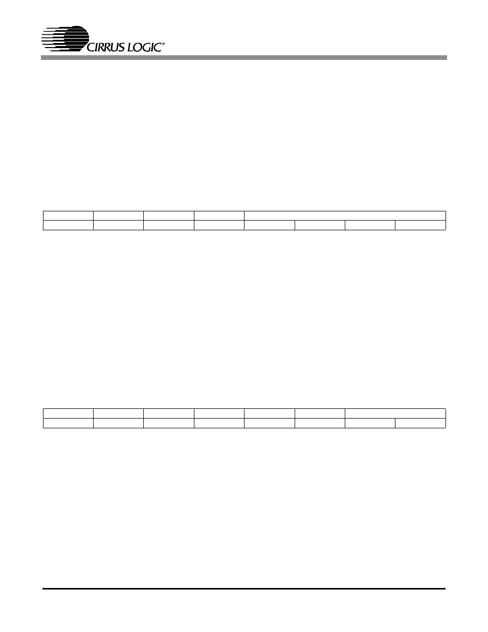
5.4
ADC Control
Address 0x03
MUTL, MUTR
ADC left and right channel mute control
*0 -
Normal
1 -
Selected ADC output muted
HPF
ADC DC offset removal. See “High Pass Filter” for more information
*0 -
Enabled
1 -
Disabled
HPFZ
ADC DC offset averaging freeze. See “High Pass Filter” for more information
*0 -
Normal. The DC offset average is dynamically calculated and subtracted from in-
coming
ADC data.
1 -
Freeze. The DC offset average is frozen at the current value and subtracted from
incoming ADC data. Allows passthru of DC information.
5.5
DAC Mute1 Control
Address 0x04
MUT6 - MUT1
Mute control for DAC6 - DAC1 respectively. When asserted, the corresponding DAC is digitally
attenuated to its maximum value (90.5 dB). When deasserted, the corresponding DAC attenu-
ation value returns to the value stored in the corresponding Digital Volume Control register. The
attenuation value is ramped up and down at the rate specified by RMP1:0.
0 -
Normal output level
*1 -
Selected DAC output fully attenuated.
RMP1:0
Attenuation ramp rate.
*0 -
0.5 dB change per 4 LRCKs
1 -
0.5 dB change per 8 LRCKs
2 -
0.5 dB change per 16 LRCKs
3 -
0.5 dB change per 32 LRCKs
7
6
5
4
3
2
1
0
MUTL
MUTR
HPF
HPFZ
RESERVED
0
0
0
0
0
0
0
0
7
6
5
4
3
2
1
0
MUT6
MUT5
MUT4
MUT3
MUT2
MUT1
RMP1
RMP0
1
1
1
1
1
1
0
0