3 anti-alias rc filters, 3 delta-sigma modulators, 1 rough-fine inputs - inr, inf – Cirrus Logic CDB5376 User Manual
Page 20: Figure 2. rc filter external components, Cdb5376
CDB5376
20
DS612DB3
2.2.2.3
Anti-alias RC Filters
The CS5372A
∆Σ modulator is 4th order and high-frequency input signals can cause instability. Simple
single-pole anti-alias RC filters are required between the CS3301A/02A amplifier outputs and the
CS5372A modulator inputs to bandwidth limit analog signals into the modulator.
The CS3301A/02A amplifier outputs are connected to external 680
Ω
series resistors and a differential
anti-alias RC filter is created by connecting 20 nF of high-linearity differential capacitance (2x 10 nF C0G)
between each half of the rough and fine signals.
2.2.3
Delta-Sigma Modulators
A single CS5372A dual modulator performs the A/D function for differential analog signals from two
CS3301A/02A amplifiers. The digital outputs are oversampled
∆Σ bit streams.
2.2.3.1
Rough-Fine Inputs - INR, INF
The modulator analog inputs are separated into rough and fine signals, each of which has an anti-alias
RC filter to limit the signal bandwidth into the modulator inputs.
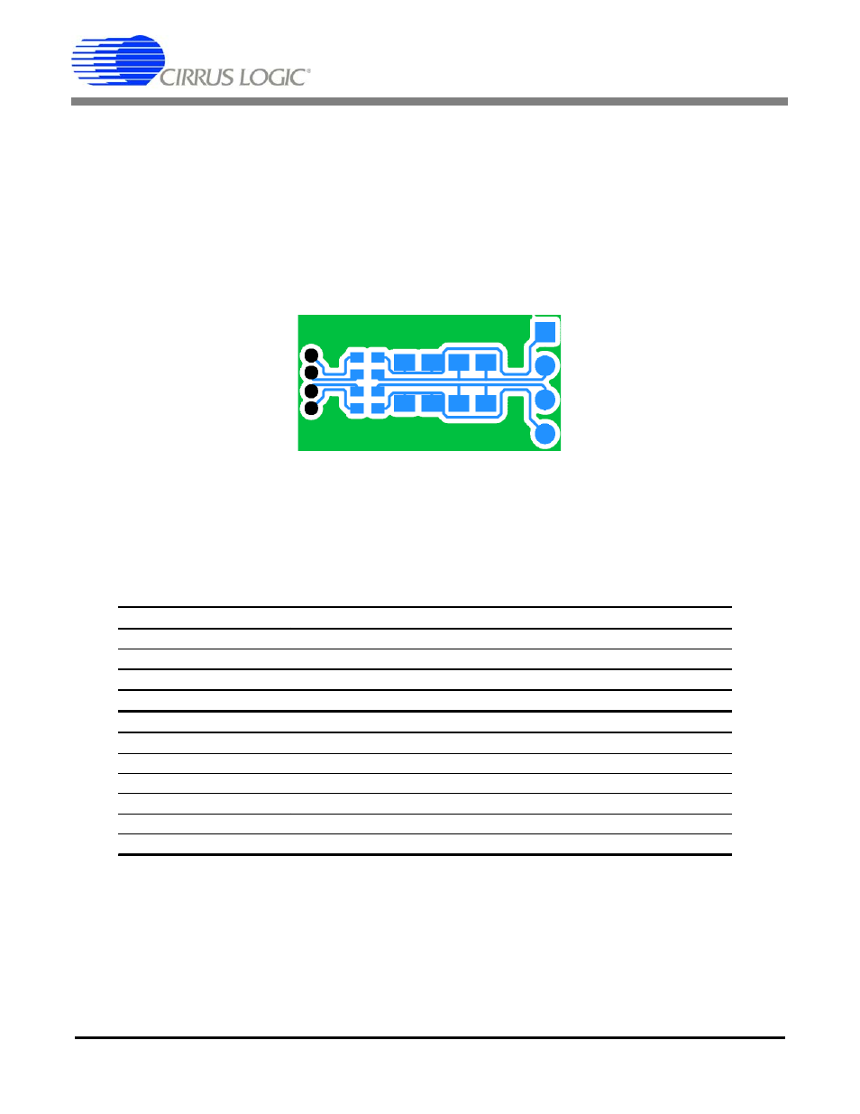
Figure 2. RC Filter External Components
INR+
INF+
INF-
INR-
INR+
INF+
INF-
INR-
Analog Signals
Description
INR1, INF1
Channel 1 analog rough / fine inputs
INR2, INF2
Channel 2 analog rough / fine inputs
VREF Voltage
reference
analog
inputs
Digital Signals
Description
MDATA[1..2]
Modulator delta-sigma data outputs
MFLAG[1..2]
Modulator over-range flag outputs
MCLK
Modulator clock input
MSYNC
Modulator synchronization input
PWDN[1..2]
Power down mode enable
OFST
Internal offset enable (+VD when using CS3301A/02A)