2 analog hardware, 1 analog inputs, 1 external inputs - ina, inb, bnc – Cirrus Logic CDB5376 User Manual
Page 16: 2 guard output, gnd connection, Table 7. screw terminal input connectors, Cdb5376
CDB5376
16
DS612DB3
2.2
Analog Hardware
2.2.1
Analog Inputs
2.2.1.1
External Inputs - INA, INB, BNC
External signals into CDB5376 are from two major classes of sensors: moving coil geophones and piezo-
electric hydrophones. Geophones are low-impedance sensors optimized to measure vibrations in land
applications. Hydrophones are high-impedance sensors optimized to measure pressure in marine appli-
cations. Other sensors for earthquake monitoring and military applications are considered as geophones
for this datasheet.
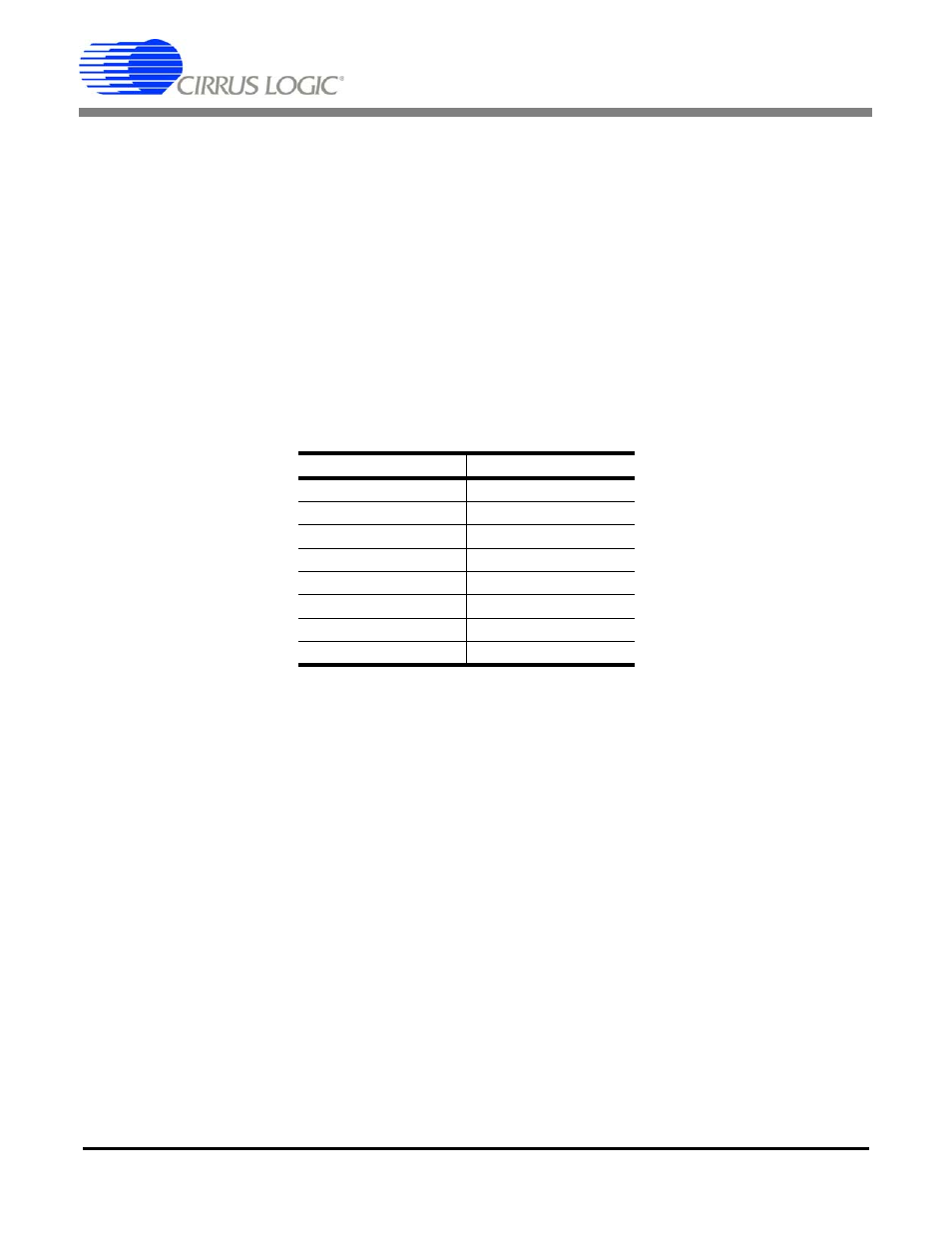
External signals connect to CDB5376 through screw terminals on the left side of the PCB. For each chan-
nel (CH1, CH2, CH3, CH4), these screw terminals make connections to two external differential inputs,
INA and INB. In addition, GND and GUARD connections are provided for connecting sensor cable shields,
if present.
BNC inputs for connecting external signals are not populated during board manufacture, but the empty
PCB footprints exist and can be installed. The inner conductors of the BNC inputs make connections to
the differential signal traces, with the outer shields connected to ground. The BNC inputs can be connect-
ed to any channel’s INA or INB inputs through the input selection jumpers.
2.2.1.2
GUARD Output, GND Connection
The CS3302A hydrophone amplifier provides a GUARD signal output designed to actively drive the cable
shield of a high impedance sensor with the common mode voltage of the sensor differential signal. This
GUARD output on the cable shield minimizes leakage by minimizing the voltage differential between the
sensor signal and the cable shield.
By default, the GUARD signal is output to screw terminals on the left side of the PCB for channels 3 and
4, which use the CS3302A amplifier. There is no GUARD signal output for channels 1 and 2 since they
use the CS3301A amplifier, so the GUARD screw terminals for these channels are left floating.
A separate GND connection screw terminal for each channel is also provided if a ground connection to
the sensor cable shield is preferred.
Signal Input
Screw Terminal
CH1 INA
J32
CH1 INB
J41
CH2 INA
J232
CH2 INB
J241
CH3 INA
J332
CH3 INB
J341
CH4 INA
J432
CH4 INB
J441
Table 7. Screw Terminal Input Connectors