6 common mode bias, Cdb5378 – Cirrus Logic CDB5378 User Manual
Page 18
CDB5378
18
DS639DB4
2.2.1.6
Common Mode Bias
Differential analog signals into the CS3301A/02A amplifiers are required to be biased to the center of the
power supply voltage range, which for bipolar supplies is near ground potential. This common mode bias
voltage is created by buffering the voltage reference, which is nominally +2.5 V relative to the VA- power
supply.
By default, CDB5378 uses the CS3301A differential geophone amplifier and so the common mode bias
resistors on the INA inputs are set for land applications. Marine applications using the CS3302A amplifier
will need to modify the default common mode bias resistors.
Resistors to create the common mode bias are normally selected based on the sensor impedance and
may need to be modified from the CDB5378 defaults depending on the sensor used. Refer to the recom-
mended operating bias conditions for the selected sensor, which are available from the sensor manufac-
turer.
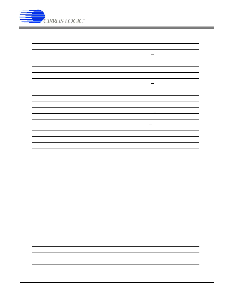
Land Common Mode Filter Specification
Value
Common Mode Capacitance
10 nF + 10%
Common Mode Resistance
200
Ω
Common Mode -3 dB Corner @ 6 dB/octave
80 kHz + 10%
Land Differential Filter Specification
Value
Differential Capacitance
10 nF + 10%
Differential Resistance
200
Ω + 200 Ω = 400 Ω
Differential -3 dB Corner @ 6 dB/octave
40 kHz + 10%
Marine Common Mode Filter Specification
Value
Hydrophone Group Capacitance
128 nF + 10%
Common Mode Resistance
825 k
Ω || 825 kΩ = 412 kΩ
-3 dB Corner @ 6 dB/octave
3 Hz + 10%
Marine Differential Filter Specification
Value
Differential Capacitance
10 nF + 10%
Differential Resistance
200
Ω + 200 Ω = 400 Ω
-3 dB Corner @ 6 dB/octave
40 kHz + 10%
Specification Value
Geophone Sensor Bias Resistance
20 k
Ω || 20 kΩ = 10 kΩ
Hydrophone Sensor Bias Resistance
18 M
Ω || 18 MΩ = 9 MΩ