Applications, 1 one time programmability, Table 1. modal and global configuration – Cirrus Logic CS2300-OTP User Manual
Page 11: 2 timing reference clock, Figure 7. external component requirements for lco, 3 frequency reference clock input, clk_in, 1 adjusting the minimum loop bandwidth for clk_in, Cs2300-otp
CS2300-OTP
DS844F2
11
5. APPLICATIONS
5.1
One Time Programmability
The one time programmable (OTP) circuitry in the CS2300-OTP allows for pre-configuration of the device
prior to use in a system. There are two types of parameters that are used for device pre-configuration: modal
and global. The modal parameters are features which, when grouped together, create a modal configuration
set (see
). Up to four modal configuration sets can be permanently stored and then
dynamically selected using the M[1:0] mode select pins (see
). The global parameters are the re-
maining configuration settings which do not change with the mode select pins. The modal and global pa-
rameters can be pre-set at the factory or user programmed using the customer development kit, CDK2000;
Please see
“Programming Information” on page 23
Table 1. Modal and Global Configuration
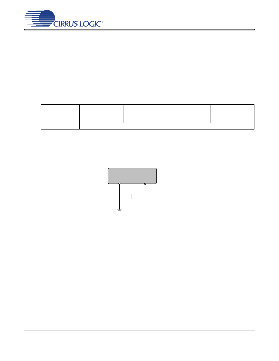
5.2
Timing Reference Clock
The internal LC oscillator is used to generate the timing reference clock. A single 0.1 µF cap must be con-
nected between the FILTP and FILTN pins and FILTN must be connected to ground as shown in
.
5.3
Frequency Reference Clock Input, CLK_IN
The frequency reference clock input (CLK_IN) is used by the Digital PLL and Fractional-N Logic block to
dynamically generate a fractional-N value for the Frequency Synthesizer (see
). The Digital PLL first compares the CLK_IN frequency to the PLL output. The Fractional-N logic
block then translates the desired ratio based off of CLK_IN to one based off of the internal LCO. This allows
the low-jitter internal LCO to be used as the clock which the Frequency Synthesizer multiplies while main-
taining synchronicity with the frequency reference clock through the Digital PLL. The allowable frequency
range for CLK_IN is found in the
“AC Electrical Characteristics” on page 7
.
5.3.1
Adjusting the Minimum Loop Bandwidth for CLK_IN
The CS2300 allows the minimum loop bandwidth of the Digital PLL to be adjusted between 1 Hz and
128 Hz using the ClkIn_BW[2:0] global parameter. The minimum loop bandwidth of the Digital PLL direct-
ly affects the jitter transfer function; specifically, jitter frequencies below the loop bandwidth corner are
passed from the PLL input directly to the PLL output without attenuation. In some applications it is desir-
able to have a very low minimum loop bandwidth to reject very low jitter frequencies, commonly referred
Parameter Type
M[1:0] pins = 00
M[1:0] pins = 01
M[1:0] pins = 10
M[1:0] pins = 11
Modal
Configuration Set 0
Ratio 0
Configuration Set 1
Ratio 1
Configuration Set 2
Ratio 2
Configuration Set 3
Ratio 3
Global
Configuration settings set once for all modes.
Figure 7. External Component Requirements for LCO
FILTN
FILTP
0.1 µF