Figure 30: modulating thermostat wiring diagram, Lonworks, Bus communication wires are used – RG CTH3-150 User Manual
Page 56
CTH3-S
ERIES
I
NSTALLATION
, O
PERATION
AND
S
ERVICE
M
ANUAL
50 of 71
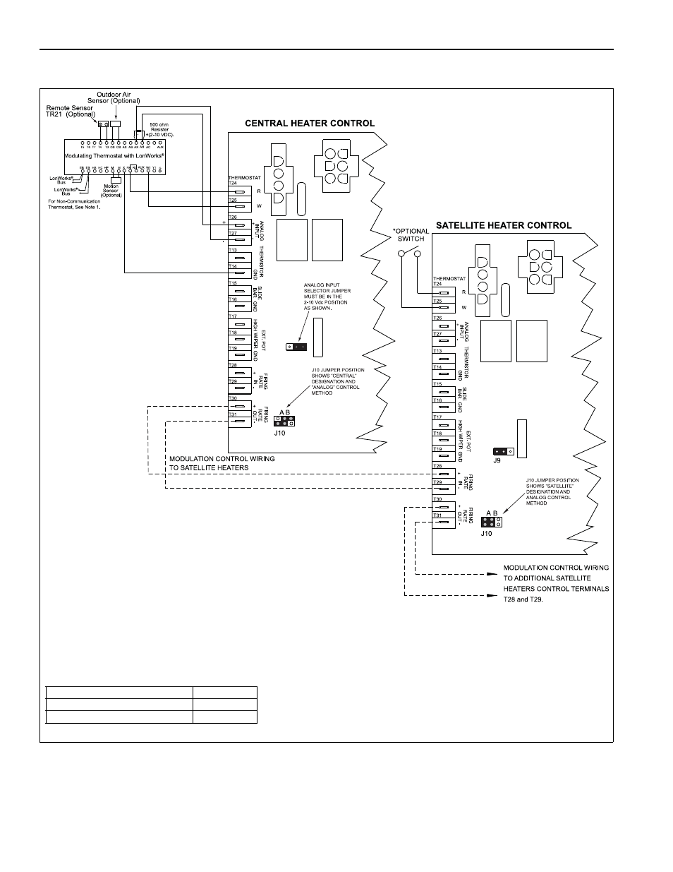
FIGURE 30: Modulating Thermostat Wiring Diagram (LonWorks
®
[2-10Vdc with 500 Ohm resistor]
optional)
* Separate on/off switch is optional for "satellite" heaters (install at user level).
On/Off switch is used to disable heater operation or reset a heater that is in "lockout" mode.
If on/off switch is not desired, leave jumper wire between R and W terminals in place.
NOTE: 1. For non-communicating thermostats without LonWorks
®
bus, thermostat terminals marked "EB"
will be marked "_____" and no LonWorks
®
bus communication wires are used.
Description
Part Number
Thermostat, modulating
90425105
Thermostat, modulating LonWorks
®
90425104