8, figure 12, Through – RG CTH3-150 User Manual
Page 14
CTH3-S
ERIES
I
NSTALLATION
, O
PERATION
AND
S
ERVICE
M
ANUAL
8 of 71
NOTE: 1. All dimensions are from the surfaces of all tubes, couplings and elbows.
2. Clearances B, C and D can be reduced by 50% after 25' (7.5 m) of tubing downstream
from where the burner and burner tube connect.
*When installed in the first 10' (3 m).
FIGURE 10: 2-FOOT DECO GRILLE AND PROTECTIVE GRILLE
(inches)
(centimeters)
Model
A
B
C
D
A
B
C
D
CTH3-80
6
38
66
38
16
97
168
97
CTH3-115
6
46
77
46
16
117
196
117
CTH3-150
6
50
80
50
16
127
204
127
CTH3-200
8
52
82
52
21
133
209
133
A
C
D
B
FIGURE 11: LOWER CLEARANCE SHIELD*
(inches)
(centimeters)
Model
A
B
C
D
A
B
C
D
CTH3-80
6
40
38
40
16
102
97
102
CTH3-115
6
54
48
54
16
138
122
138
CTH3-150
6
55
50
55
16
140
127
140
CTH3-200
- UNAPPROVED -
- UNAPPROVED -
A
C
D
B
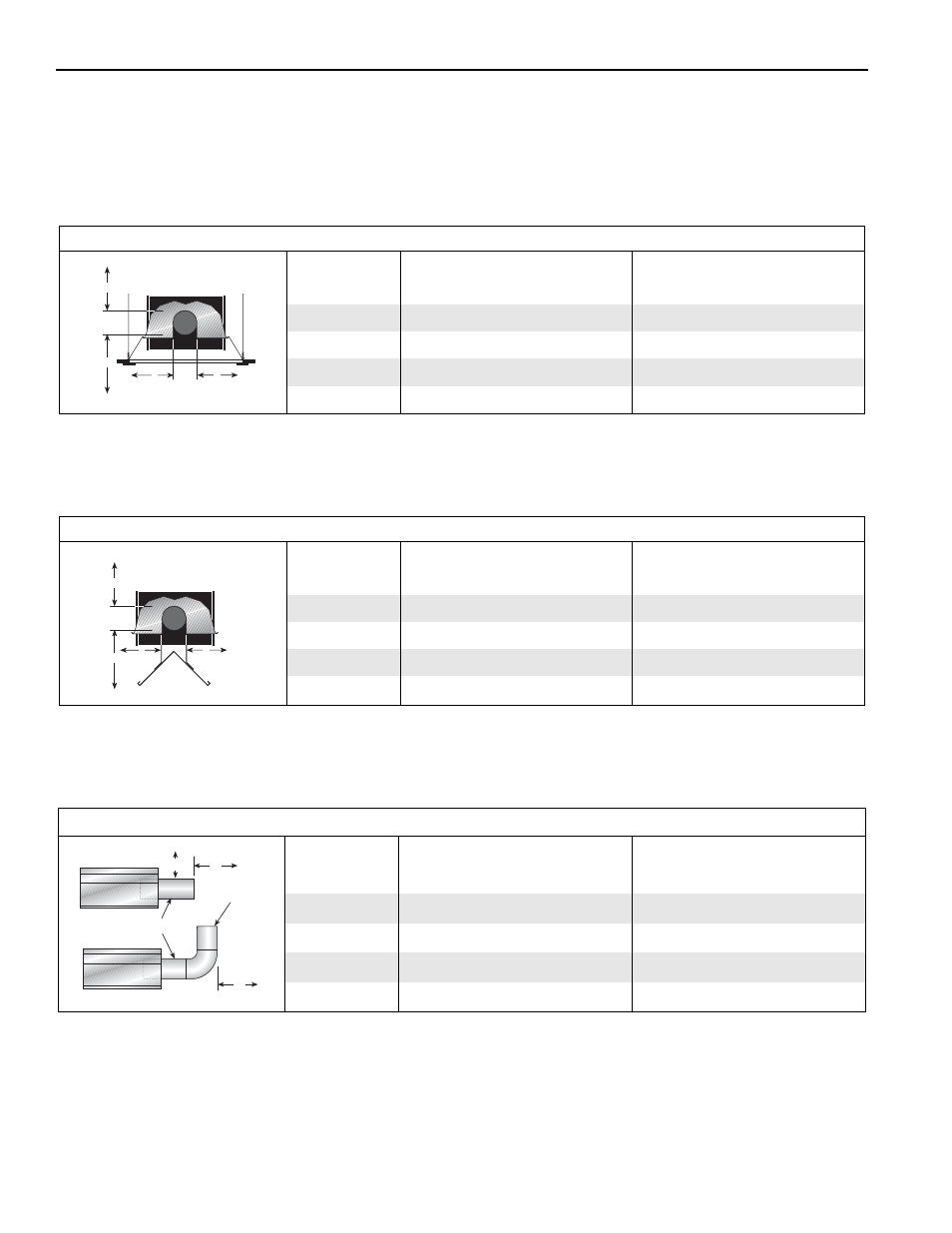
FIGURE 12: VENTING
(inches)
(centimeters)
Model
A
E
F
A
E
F
CTH3-80
20
24
18
51
61
46
CTH3-115
20
24
18
51
61
46
CTH3-150
20
30
18
51
77
46
CTH3-200
20
30
18
51
77
46
Radiant Tubes
Vent
Pipes
Unvented
Vented
A
E
F