Figure 14: critical hanger placement, 13, figure 14, Typical suspension details – RG CTH3-150 User Manual
Page 19
SECTION 6: H
EATER
I
NSTALLATION
13 of 71
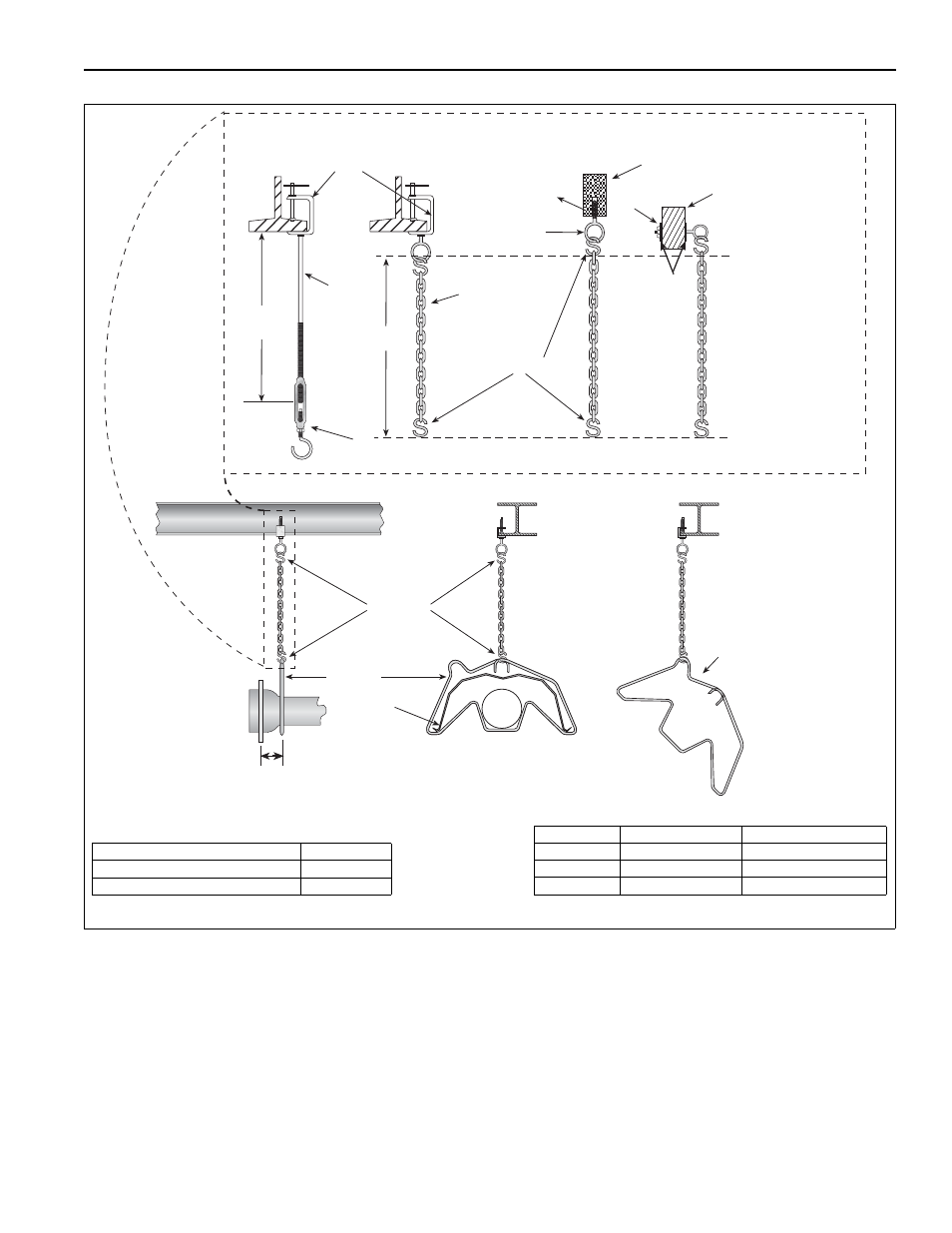
FIGURE 14: Critical Hanger Placement
Hanger
Side View
Must Be Within 4" (10 cm)
Front View
S-hooks
Reflector
Hanger
45° Angle
* Allows for thermal expansion of system
Typical Suspension Details
Rod 3/8"
Beam Clamp
Concrete Beam
Wood Beam
Washers
Locknut
Screw Hook
3/8"
24" min.*
(61 cm)
X*
Anchor
S-hooks
Chain Size
3/16"
Minimum
Turnbuckle
Not Included
Description
Part Number
S-Hook
91907302
Tube/Reflector Hanger
03090100
Run Length
Typical Expansion
Minimum “X” Length
10' - 50'
±1" (3 cm)
12"
51' - 60'
±2" (5 cm)
18"
61' - 70'
±3" (8 cm)
24"