WIKA DPS40 User Manual
Page 12
GB
WIKA operating instructions DELTA-plus, DELTA-comb and DELTA-switch
12
14093265.01 03/2014 GB/D/F/E
14077608.01
⊖
⊕
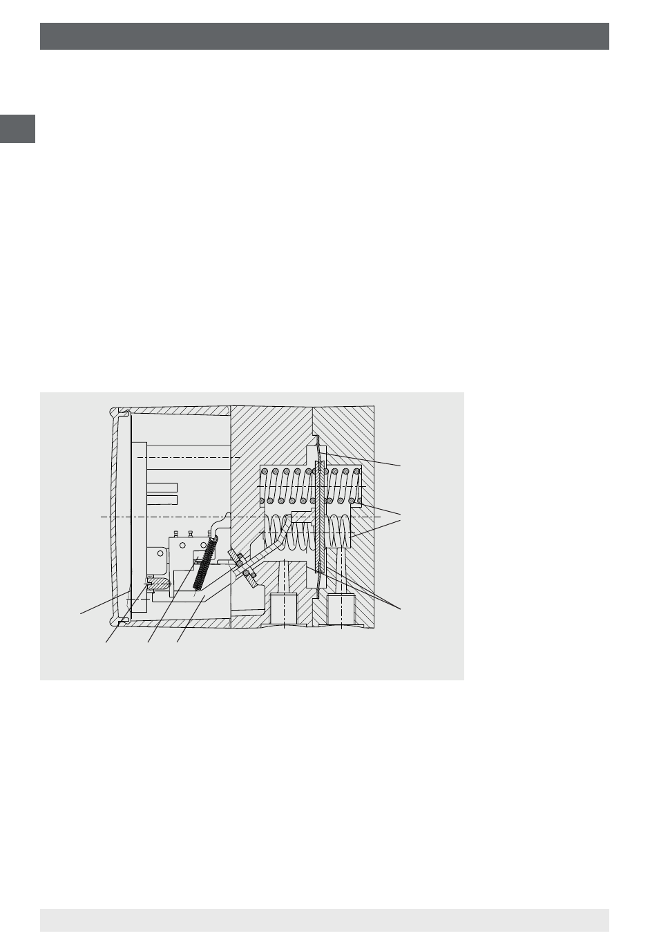
DELTA-switch model DPS40
Pressures p
1
and p
2
act on the media chambers ⊕ and ⊖, which are separated
by an elastic diaphragm (1).
The differential pressure (∆p = p
1
- p
2
) leads to an axial deflection of the
diaphragm against the measuring range springs (2).
The deflection, which is proportional to the differential pressure, is transmitted to
the leaf springs of the micro switches (4) in the switch case via a pressure-tight
and low-friction rocker arm (3).
Overpressure safety is provided by metal bolsters (5) resting against the elastic
diaphragm.
The adjustment of the switch point is made by the adjustment screws accessi-
ble from the front (6). The assistant scales (7) enable an accurate setting of the
switch points and indicate the current set point.
4.2 Scope of delivery
Cross-check scope of delivery with delivery note.
4. Design and function