Commissioning, operation – WIKA O-10 User Manual
Page 24
24
WIKA operating instructions pressure transmitter model O-10
GB
11613017.04 05/2013 GB/D/F/E
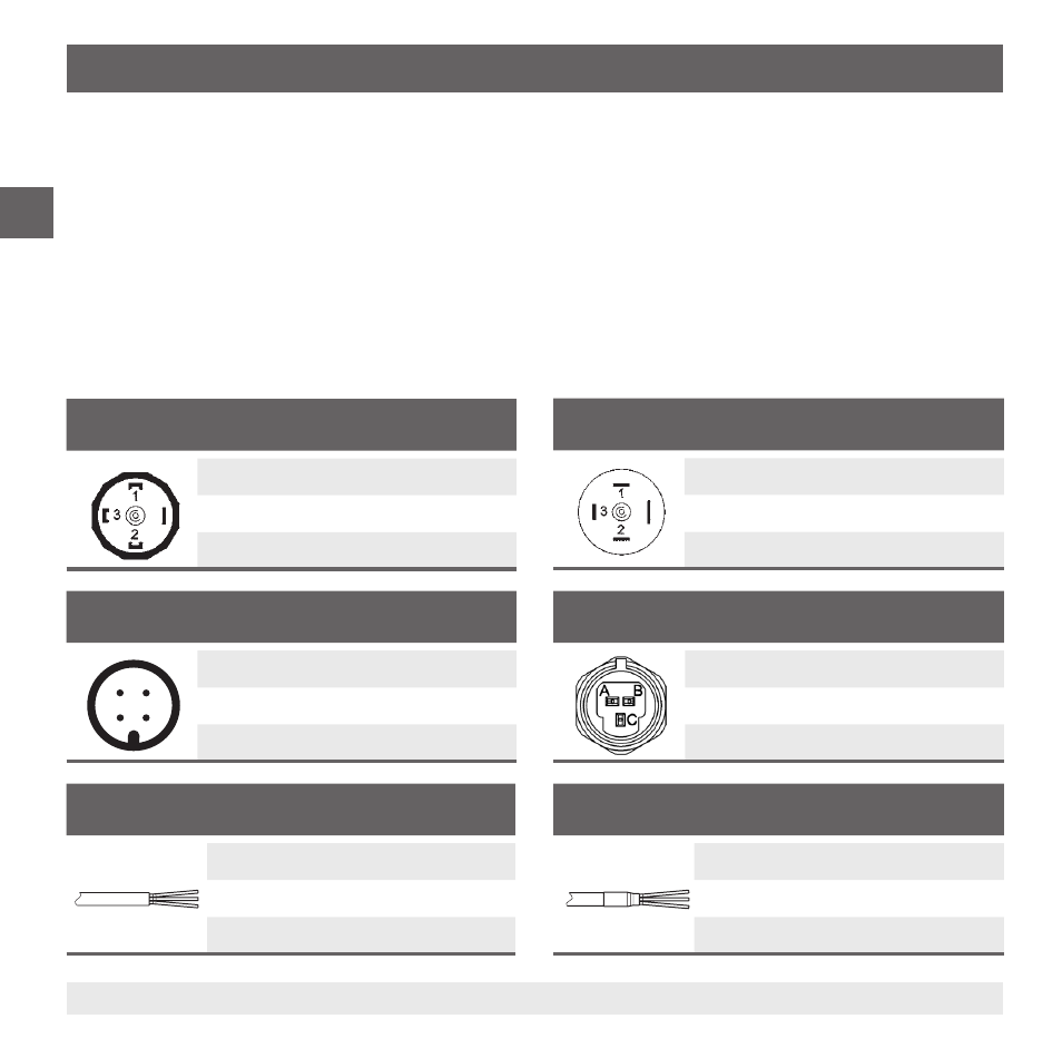
Circular connector M12 x 1
2-wire
3-wire
4
3
1
2
U
B
1
1
0V
3
3
S
+
-
4
Angular connector DIN 175301-803 A
2-wire
3-wire
U
B
1
1
0V
2
2
S
+
-
3
Angular connector DIN 175301-803 C
2-wire
3-wire
U
B
1
1
0V
2
2
S
+
-
3
Cable outlet, shielded
2-wire
3-wire
U
B
brown
brown
0V blue
blue
S
+
-
black
Cable outlet, unshielded
2-wire
3-wire
U
B
brown
brown
0V green
green
S
+
-
white
Metri-Pack series 150
2-wire
3-wire
UB B
B
0V
A
A
S+
-
C
6. Commissioning, operation
■
With instruments with internally connected shields (only connector variants) the cable shield should
be grounded at one end. The simultaneous connection of the case and the cable shield to ground
is only permitted if any accidental energisation between the shield connection (e.g. at the power
supply) and the case can be excluded (see EN 60079-14).
■
For the output signals DC 0 ... 5 V, DC 1 ... 5 V, DC 0.5 ... 4.5 V and DC 0.5 ... 4.5 V ratiometric, the
following applies in addition: If the cable of the electrical connection is longer than 30 m or leaves
the building, then the pressure transmitter should be used with a shielded cable. Earth the shield on
at least one end of the lead.
Connection diagrams