Figure 3: wp-110 xga line transmitter – Kramer Electronics PT-120 User Manual
Page 11
8
PT-110xl, WP-110, PT-120, TP-120 - WP-110 XGA Line Transmitter
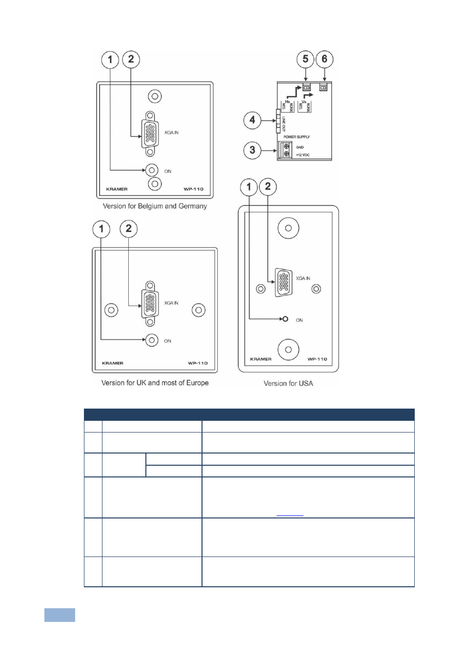
Figure 3: WP-110 XGA Line Transmitter
#
Feature
Function
1
ON LED
Illuminates when receiving power
2
XGA IN 15-pin HD (F)
Connector
Connect to the XGA source
3
POWER
SUPPLY
GND PIN
Connect (-) to the Ground
+12V DC PIN
Connect (+) to the connector for powering the unit
4
LINE OUT RJ-45
Connector
Connects to the LINE IN RJ-45 connector on the PT-120 or
TP-120 XGA Line Receiver
Use a UTP cable with CAT 5 connectors at both ends (the
PINOUT is defined in
5
HS Switch
Slide the switch to the left (by default, both switches are set
to the right) to change the HS (horizontal sync) polarity to
(NEG.) negative polarity (down-going syncs); slide the
switch to the right (NORM.) to retain the polarity
6
VS Switch
Slide the switch to the left to change the VS (vertical sync)
polarity to (NEG.) negative polarity; slide the switch to the
right (NORM.) to retain the polarity