6 connecting the wall plates, Connecting the wall plates, Figure 3: connecting the sv-301 to the sv-551 – Kramer Electronics SV-551ALC User Manual
Page 18
Defining the SV-551 SummitView™ Processor/Switcher
15
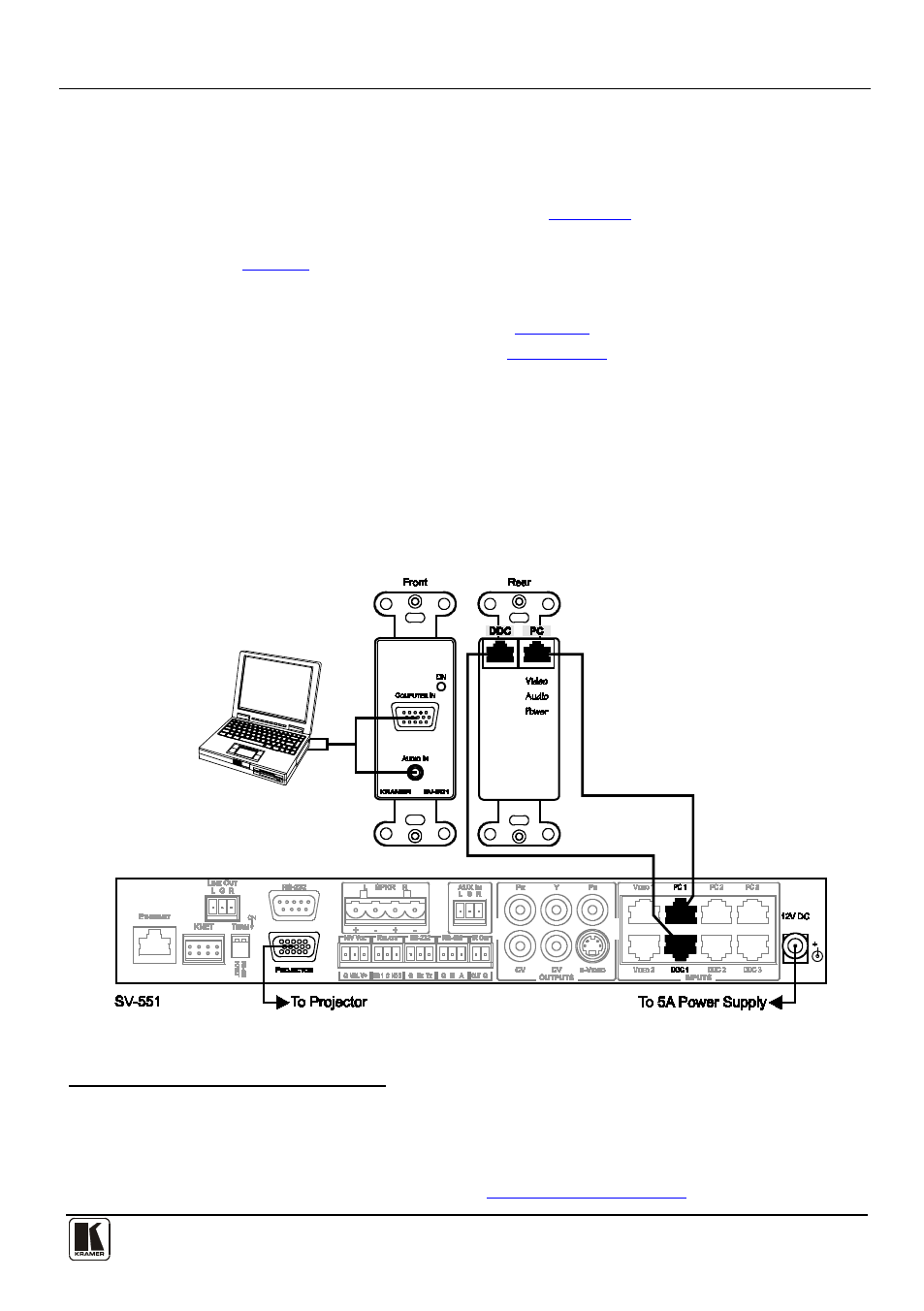
4.6 Connecting the Wall Plates
The wall plates should be connected to the corresponding inputs on the SV-551
using the supplied or optional STP cables
(see
). The SV-301 has two
RJ-45 CAT 5 connectors (one for DDC and one for PC (Video/Audio/Power (US
version)), as
defines, and comes with two STP cables. The SV-302 has one
RJ-45 CAT 5 connector (U.S. version) and comes with one STP cable.
To connect the SV-301, as the example in
separate color illustration referred to in
Section 5.6
):
1. Connect the computer graphics source (for example, a laptop) to the Computer In
15-pin HD connector and to the unbalanced stereo Audio In 3.5mm mini jack on
the front of the SV-301, for example, using a Kramer C-GMA/GMA cable (VGA
HD15M +Audio jack to VGA HD15M +Audio jack)
2. On the rear of the SV-301, connect the RJ-45 CAT 5 connector marked:
“DDC” to the DDC 1 INPUT on the SV-551
“PC” to the PC 1 INPUT on the SV-551
Figure 3: Connecting the SV-301 to the SV-551
1 There are two types of STP cable provided with SummitView™: CP-STP-50 (plenum-rated for the SummitView™ US) or C-STP-50
(non-plenum for the SummitView™ Europe). Other STP cables can also be used. However, when using longer STP cables, image
quality can be impaired
2 Not supplied. The complete list of Kramer cables is on our Web site