2 the rc-63dln room controller rear panel, 1 the rc-63dln rear panel version for the usa, The rc-63dln room controller rear panel – Kramer Electronics RC-63DLN User Manual
Page 9: Figure 2: rc-63dln rear panel for the usa
6
RC-63DLN - Overview
3.2
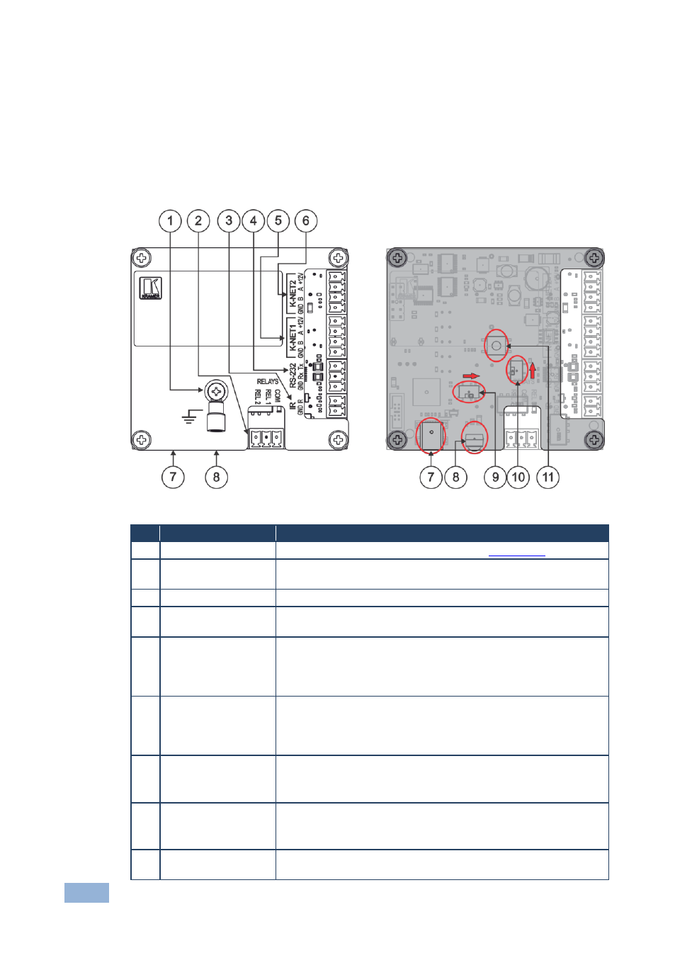
The RC-63DLN Room Controller Rear Panel
This section defines the rear panel of the RC-63DLN.
3.2.1
The RC-63DLN Rear Panel Version for the USA
This section shows the rear panel of the RC-63DLN USA version.
Figure 2: RC-63DLN Rear Panel for the USA
#
Feature
Function
1
Grounding Screw
Connect to grounding wire (optional), see
Section
2
RELAY Ports
2 relay connections (REL 1 and REL 2). Connect to room items
(such as lighting, screen settings, and so on)
3
IR Port
Control a machine via an IR Emitter
4
RS-232 Port (GND,
Rx, Tx)
Connect to the RS-232 connector on the A/V equipment or a PC
or other serial controller
5
K-NET1 Connector
Connect the GND pin to the Ground connection; pin B (-) and pin
A (+) are for RS-485, and the +12V pin is for powering the unit
The ground connection is sometimes connected to the shield of the
RS-485 cable
6
K-NET2 Connector
Connect the GND pin to the Ground connection; pin B (-) and pin
A (+) are for RS-485, and the +12V pin is for powering the unit
The ground connection is sometimes connected to the shield of the
RS-485 cable
7
PROGRAM (USB)
Connector
Connect to a computer for firmware upgrade or setting the
K-NET ID number
The USB port is accessible from the side
8
IR IN built-in IR
Receiver
Use to learn the IR commands from
a machine’s remote control
transmitter
The IR receiver is accessible from the side
9
PROG Switch
For technical support use only (should be set to the right in the
direction of the arrow for normal operation)