Kramer Electronics RC-63DLN User Manual
Page 11
8
RC-63DLN - Overview
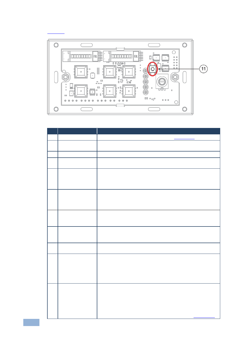
shows the location of the Reset to Default button:
Figure 4: RC-63DLN European Version, Reset to Default Button
#
Feature
Function
1
Grounding Screw
Connect to grounding wire (optional), see
Section
2
RELAY Ports
2 relay connections (REL 1 and REL 2). Connect to room items
(such as lighting, screen settings, and so on)
3
IR Port
Control a machine via an IR Emitter
4
RS-232 Port (GND,
Rx, Tx)
Connect to the RS-232 connector on the A/V equipment or a PC
or other serial controller
5
K-NET1 Connector Connect the GND pin to the Ground connection; pin B (-) and pin
A (+) are for RS-485, and the +12V pin is for powering the unit
The ground connection is sometimes connected to the shield of the
RS-485 cable
6
K-NET2 Connector Connect the GND pin to the Ground connection; pin B (-) and pin
A (+) are for RS-485, and the +12V pin is for powering the unit
The ground connection is sometimes connected to the shield of the
RS-485 cable
7
IR IN built-in IR
Receiver
Use to learn the IR commands from a machine’s remote control
transmitter
The IR receiver is accessible from the side
8
PROGRAM (USB)
Connector
Connect to a computer for firmware upgrade or setting the K-NET
ID number
The USB port is accessible from the side
9
PROG Switch
For technical support use only (should be set upwards in the
direction of the arrow for normal operation)
10 K-NET TERM
Switch
Slide upwards (in the direction of the arrow) for K-NET
termination, slide downwards to leave bus unterminated. The last
physical device on a K-NET bus must be terminated
You can reach the KNET termination switch by inserting a small
screwdriver into the gap between the rear panel PCB and the metal
rear panel cover.
11 RESET TO
DEFAULT Button
Disconnect the power and then connect it while pressing the
RESET TO DEFAULT button (using a small screwdriver). The unit
will power up and load its memory with the factory default KNET
ID auxiliary setting (ID=2).
This operation should be carried out by authorized Kramer technical
personnel or by a qualified system integrator.
You can access the button by removing the faceplate (see
Section