Kramer Electronics VS-801xlm User Manual
Page 13
KRAMER ELECTRONICS LTD.
12
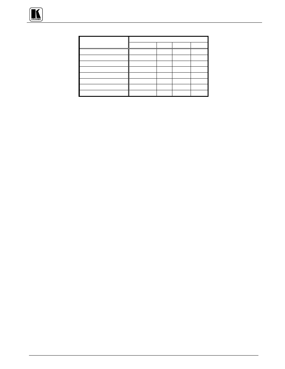
Table : DIP Switch Settings
DIP Switch #
Switcher #
1 (Reply)
2
3
4
Machine 1 (Master)
ON
ON
ON
ON
Machine 2 (Slave)
ON or OFF
ON
ON
OFF
Machine 3 (Slave)
ON or OFF
ON
OFF
ON
Machine 4 (Slave)
ON or OFF
ON
OFF
OFF
Machine 5 (Slave)
ON or OFF OFF
ON
ON
Machine 6 (Slave)
ON or OFF OFF
ON
OFF
Machine 7 (Slave)
ON or OFF OFF
OFF
ON
Machine 8 (Slave)
ON or OFF OFF
OFF
OFF
NOTE
The Slave "Reply" settings are all ON or all OFF, depending on the requirements of the system (see detailed
configuration in section 12.4-12.6). The Master "Reply" setting is always ON.
9.2 Jumpers, their Uses and Set-up Requirements
The switcher has additional adjustments and settings. These include the internal jumpers.
WARNING!
Mains voltage is accessible inside the switcher, so always turn off the switcher and
remove its power cable from the mains socket before removing its cover.
The jumper locations are illustrated in Figure , and their functional operation is described below:
Each switcher input has its own internal jumper. In the VS-1211, these jumpers are numbered J21 to J33
and they are factory located in the position that provides a 75ohm input termination. If the 75ohm
termination is not required, the jumper must be relocated to its alternate position (floating on the pin
remote from the input socket and not connected in any circuit). The particular input is now "High-Z" (not
75ohm terminated) and may be used for looping.
When two VS-1211 switchers are to be interconnected to provide a 12 input, 2 output (12x2)
configuration by looping Input #1 of switcher #1 to Input #1 of switcher #2, etc., J35 must be located in
its alternate position in all of the switchers. This is also the case for configurations 12x3, 12x4, etc., using
3, 4, or more switchers.
When two VS-1211 switchers are to be interconnected to provide a 24 input, 1 output (24x1)
configuration, J35 must be located in its factory set position in all of the switchers. This is also the case
for configurations 36x1, 48x1, etc., using 3, 4, or more switchers.
Jumper J20 is used to define the Sync video source for all the switcher inputs, so that Vertical Interval
Switching can be assured. The jumpers are factory located for an External Sync source. If the sync of the
video source on Input #1 is preferred, then J20 must be relocated to its alternate position in any one of
the switchers.
When switchers are to be interconnected, the switcher that contains the active video sync source must be
identified to all the switchers so that it can be sensed by all of them and thus ensure Vertical Interval
Switching throughout. J34 is the jumper to be used for this task. It is factory located to identify the
switcher in which it sits. Thus, in the switcher to which the active sync source will be connected, the
jumper must be left in the factory located position. In all the other switchers in the interconnected
complex, J34 must be relocated in its alternate position.