Kramer Electronics VS-801xlm User Manual
Page 11
KRAMER ELECTRONICS LTD.
10
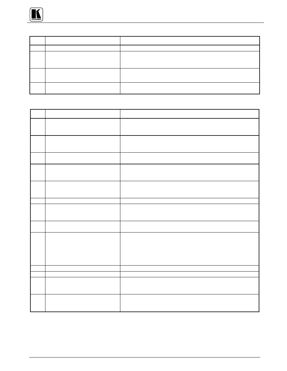
Table : VS-1211/1201/1001xlm Front Panel Features
No.
Feature
Function
1.
POWER Switch
Illuminated switch: Supplies power to the unit.
2.
INPUT SELECTOR pushbuttons
Each input may be selected by the corresponding input select button.
The buttons illuminate when pressed and the illuminated input select
button identifies the active input.
3. Internal cable EQ. trimmer
Internally located and accessed through hole in the switcher base. It
allows, if necessary, to control cable equalization.
4. Internal
LEVEL trimmer
Internally located and accessed through hole in the switcher base. It
allows, if necessary, to adjust switcher output signal level.
Table : VS-1211/1201/1001xlm Rear Panel Features
No.
Feature
Function
1.
AUDIO L snap fit terminal blocks
for the
"11" group or RCA
connectors for the
“01xl” group.
12, 10, 8, 6 or 4 left channel inputs used to connect the appropriate
number of stereo audio input sources 1-12. (see Figure ).
2.
OUT L snap fit terminal blocks for
the
"11" group or RCA connector
for the
“01xl” group.
Left channel audio output (3 outputs for “ xlm” series).
3.
RS-485 Two-part, snap fit terminal
block
Used for bi-directional communication with another switcher or PC
through RS-485 interface.
4.
AUDIO R snap fit terminal blocks
for the
"11" group or RCA
connectors for the
“01xl” group.
12, 10, 8, 6 or 4 right channel inputs used to connect the appropriate
number of stereo audio input sources 1-12.
5.
OUT R snap fit terminal blocks for
the
"11" group or RCA connector
for the
“01xl” group.
Right channel audio output (3 outputs for “ xlm” series).
6.
Ext. Sync BNC connector
Connection of an external sync/composite video input.
7.
IN1-IN12 BNC connectors
12, 10, 8, 6 or 4 video inputs used to connect the appropriate number
of composite or single video input sources, including cameras,
VCRs. Supported formats: composite/single component video.
8.
OUT BNC connector (s)
Video output having same connector and formats as the input (3
outputs for “ xlm” series).
9. DB-9 female
To PC connector
Used for control of the switcher from a PC or remote control panel,
through RS-232 interface.
NOTE
Operation of the switcher from a remote PC may be
performed by the K-Switch Software provided with
the switcher.
10.
REMOTE DB-15 connector
Used for remote contact closure control (see Figure ).
11.
To Next DB-9 connector
Used for looping to the next switcher.
12.
SETUP DIP switches
Allow proper configuration of the control signals received and
transmitted through the RS-232 (or RS-485) control port,
master/slave configurations, and device ID numbers.
13. Power Connector
A 3-prong AC connector allows power to be supplied to the unit.
Directly underneath this connector, a fuse holder houses the
appropriate fuse.