Table 5: delay dip-switch settings, 2 setting the machine # dip-switches, Table 6: machine # dip-switch settings – Kramer Electronics VP-8x4 User Manual
Page 16
Connecting the VP-8x4 8x4 VGA / UXGA Matrix Switcher
13
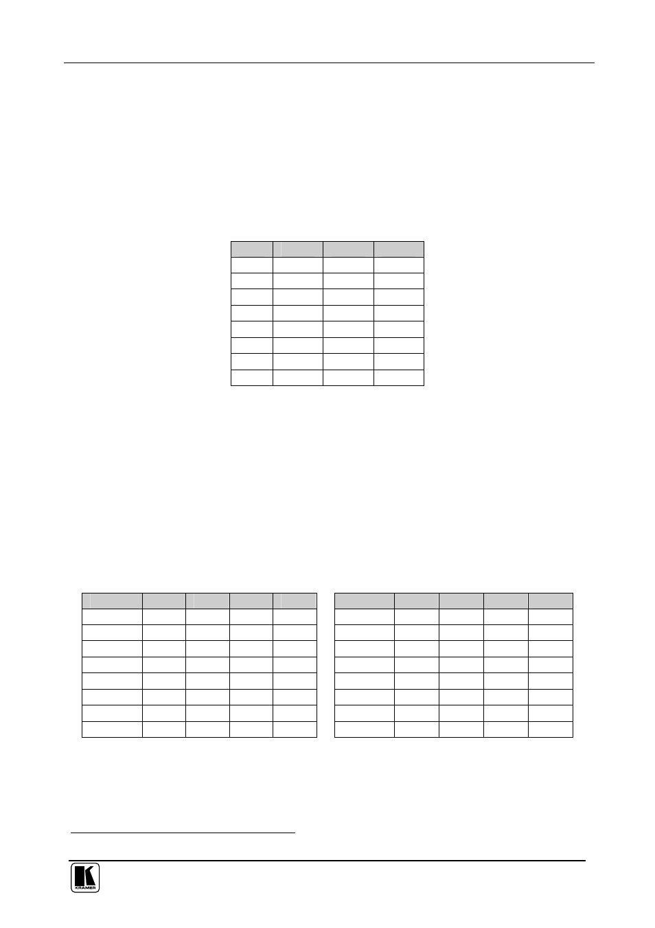
6.5.1 Setting the Delay
You can achieve clean transitions when switching between non-genlocked
sources by setting the delay time—ranging from 0 sec to 3.5 sec
1
—via the
DELAY DIP-switches, as Table 5 defines. The
VP-8x4 unit is shipped (its
factory default state) with no delay, that is, the DELAY DIP-switches are set up
for a 0 sec delay. The delay time is the period where the output will be forced
to black when switching between inputs.
Table 5: DELAY DIP-switch Settings
sec
DIP 1
DIP 2
DIP 3
0
OFF
OFF
OFF
0.5
OFF
OFF
ON
1.0
OFF
ON
OFF
1.5
OFF
ON
ON
2.0
ON
OFF
OFF
2.5
ON
OFF
ON
3.0
ON
ON
OFF
3.5
ON
ON
ON
6.5.2 Setting the Machine # DIP-switches
The Machine # determines the address of a
VP-8x4 unit, specifying which
VP-8x4 unit is being controlled when several VP-8x4 units are connected to a
PC or serial controller. Set the Machine # on a
VP-8x4 unit via MACH# DIPs
4, 5, 6 and 7, according to Table 6.
When using a standalone
VP-8x4 unit, set the Machine # to 1. When
connecting more than one
VP-8x4 unit, set the first machine (the Master) that
is closest to the PC, as Machine # 1 (DIP-switches are set to OFF).
Table 6: Machine # DIP-switch Settings
Mach. #
DIP 4
DIP 5
DIP 6
DIP 7
Mach. #
DIP 4
DIP 5
DIP 6
DIP 7
1
OFF
OFF
OFF
OFF
9
ON
OFF
OFF
OFF
2
OFF
OFF
OFF
ON
10
ON
OFF
OFF
ON
3
OFF
OFF
ON
OFF
11
ON
OFF
ON
OFF
4
OFF
OFF
ON
ON
12
ON
OFF
ON
ON
5
OFF
ON
OFF
OFF
13
ON
ON
OFF
OFF
6
OFF
ON
OFF
ON
14
ON
ON
OFF
ON
7
OFF
ON
ON
OFF
15
ON
ON
ON
OFF
8
OFF
ON
ON
ON
16
ON
ON
ON
ON
1 In increments of 0.5sec