1 connecting the remote terminal block connector, Connecting the remote terminal block connector, Figure 2 – Kramer Electronics VP-211K User Manual
Page 10
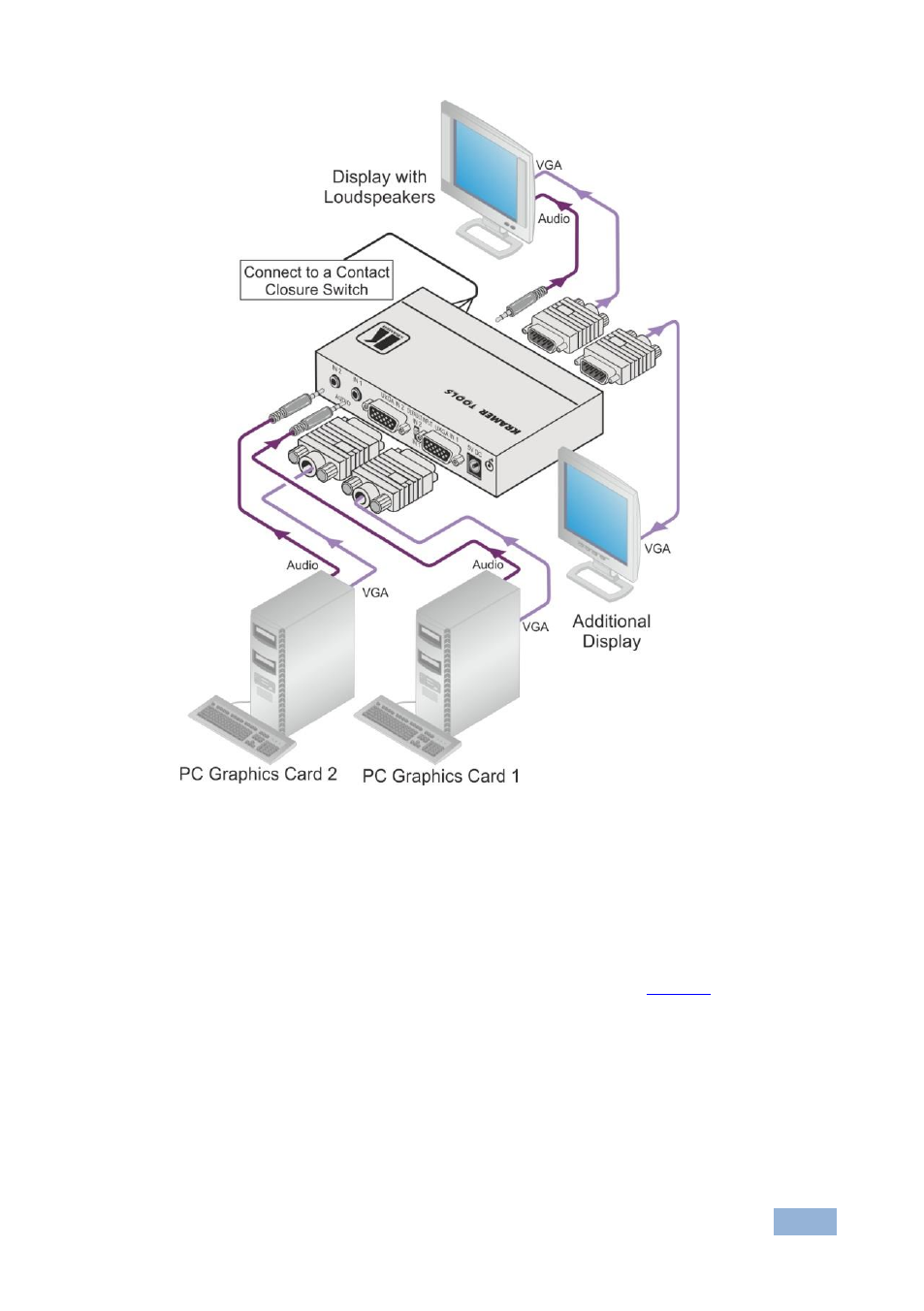
VP-211K - Connecting the VP-211K
7
Figure 2: Connecting the VP-211K Automatic UXGA / Audio Switcher
4.1
Connecting the REMOTE Terminal Block Connector
You can force the routing of one of the two inputs to the UXGA output by remote
control. To do so, connect the appropriate REMOTE input terminal block
connector pins to a contact closure switch. For example, as
route REMOTE IN1 to the UXGA output, connect PIN IN1 to PIN G (ground). To
route REMOTE IN2 to the UXGA output, connect PIN IN2 to PIN G.
Note that the connection should be permanent, since the VP-211K reverts to an automatic
switcher when the connection is removed.
See also other documents in the category Kramer Electronics Routers:
- VM-216H (25 pages)
- VM-28H (23 pages)
- VM-22H (12 pages)
- VM-24H (23 pages)
- VM-24HC (21 pages)
- VM-24HD (10 pages)
- VM-24HDCP (19 pages)
- VM-42 (8 pages)
- VP-222K (10 pages)
- VP-242 (8 pages)
- VP-32K (13 pages)
- VS-202YC (23 pages)
- 4x1S (15 pages)
- 4x1V (12 pages)
- 6241HDxl (10 pages)
- 6241N (10 pages)
- 6502 (12 pages)
- PT-201VGA (8 pages)
- TailorMade (21 pages)
- TailorMade (22 pages)
- VP-1201 (50 pages)
- VP-12x8 (34 pages)
- VP-1608 (46 pages)
- VS-88SDI (42 pages)
- VP-321xl (37 pages)
- VP-16x18AK (60 pages)
- VP-201xl (8 pages)
- VP-27 (32 pages)
- VS-66HN (25 pages)
- VS-88HDxl (43 pages)
- VP-28 (42 pages)
- VP-2x2 (17 pages)
- VP-31 (25 pages)
- VP-311DVI (20 pages)
- VS-88HD (21 pages)
- VS-88HD (44 pages)
- VP-31KSi (16 pages)
- VP-81KSi (51 pages)
- VP-31KSi (48 pages)
- VP-41 (8 pages)
- VP-411DS (22 pages)
- VS-81HDxl (25 pages)
- VP-4x1CS (39 pages)
- VP-4x4K (61 pages)