Defining the vm-24hc 2 input 1:4 hdmi distributor, Figure 1: vm-24hc 2 input 1:4 hdmi distributor – Kramer Electronics VM-24HC User Manual
Page 8
VM-24HC - Overview
5
3.1
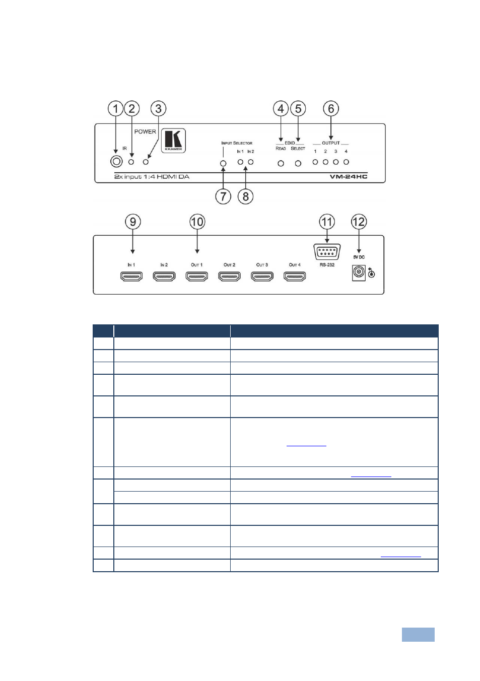
Defining the VM-24HC 2 Input 1:4 HDMI Distributor
This section defines the VM-24HC.
Figure 1: VM-24HC 2 Input 1:4 HDMI Distributor
#
Feature
Function
1
IR Receiver
IR signal sensor for the IR remote control
2
IR LED
Lights yellow when the device receives an IR signal
3
POWER LED
Lights green when the device receives power
4
EDID READ Button
Press to acquire the EDID following selecting the EDID
source. Press again to indicate the EDID status
5
EDID SELECT Button
Press to select the EDID source (single output, Auto-
Mix or default)
6
OUTPUT LEDs (1 to 4)
Lights green when an output is connected and active.
LED flashes to indicate the source of the EDID
acquired (see
Section
) or when connecting a
non-HDCP display while providing HDCP content to
the VM-24HC
7
INPUT SELECTOR Button
Press to select Input 1 or 2 (see
Section
8
IN 1 LED
Lights green when Input 1 is selected
IN 2 LED
Lights green when Input 2 is selected
9
INPUT 1 and INPUT 2 HDMI
Connectors
Connect to the HDMI sources 1 and 2
10
OUTPUT 1 to OUTPUT 4
HDMI Connectors
Connect to the HDMI acceptors 1 to 4
11
RS-232 9-pin D-sub Port
Connects to a PC/remote controller (see
Section
12
5V DC Power Connector
Connects to the power adapter, center pin positive