Kramer Electronics RC-IR2 User Manual
Page 9
KRAMER: SIMPLE CREATIVE TECHNOLOGY
Your Remote Receiver
6
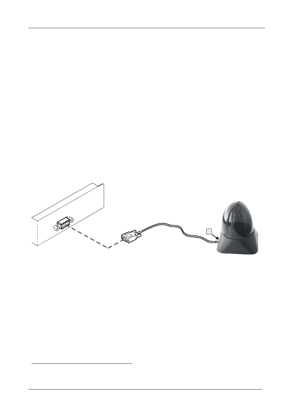
To connect the external remote receiver, as the example in Figure 3 illustrates,
do the following:
1. Connect the external remote receiver to the RS-232 port on the Kramer
switcher, via
one of the following methods:
A direct one-to-one connection, by simply connecting the attached
RS-232 cable’s 9-pin D-sub connector to the RS-232 9-pin D-sub
port on the switcher
An extended (up to about 25 meters) one-to-one connection, by
connecting a flat cable, or by just connecting PIN # 2 to PIN # 2, PIN
# 3 to PIN # 3, and PIN # 5 to PIN # 5 (ground) between the attached
RS-232 cable’s 9-pin D-sub connector and the RS-232 9-pin D-sub
port on the switcher
A cross connection (or Null-modem adapter) when required. For the
cross connection, connect PIN # 2 to PIN # 3, PIN # 3 to PIN # 2,
and PIN # 5 to PIN # 5
2. Connect the 12V DC power adapter to the power socket and connect the adapter
to the mains electricity.
Connect to the
RS-232 Port on
the Kramer Switcher
Power
+12V DC
Figure 3: Connecting the External Remote Receiver
When using more than one unit, connect the RS-485 detachable terminal
block connectors between the different switchers. The units must belong to the
same group and the same series
1
but can be different models
2
.
1 For example, vertical interval matrix switchers for composite video and stereo audio signals
2 For example, the VS-808xl and the VS-606xl